Home/
Registry/
Ford/
Taurus/
1992-1995/
1993 Ford Taurus/
Photo
supermotors.net/registry/media/593148
Ford Taurus SHO JBL Radio Wiring Diagram (No CD): Amplifier & Subwoofer 130-8

Reference · 1992-1995 TaurusAll 37 wiring diagrams
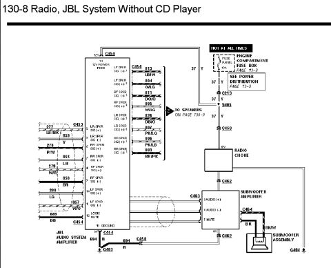
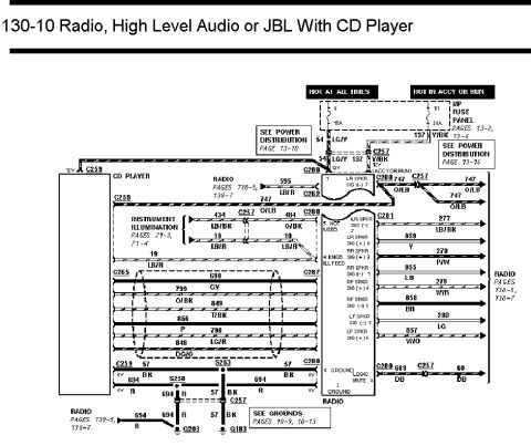
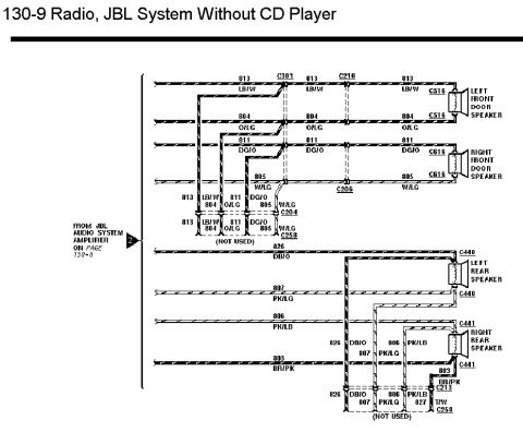

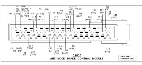
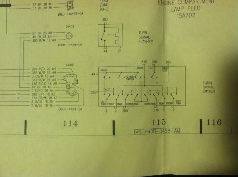
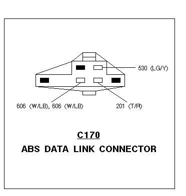
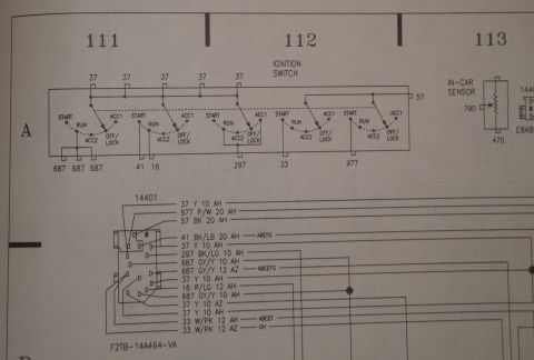

Wiring diagram for the JBL radio system without CD player showing amplifier, radio choke and subwoofer connections.
Part of 1992-1995 Ford Taurus Wiring Diagrams
This document is page 130-8 of a Ford factory wiring diagram titled "Radio, JBL System Without CD Player." It shows the JBL Audio System Amplifier with its connectors C453 and C454, including pin numbers, circuit numbers, and wire colors for all four speaker-level inputs (LF, RF, LR, RR, circuits 277-280 and 855-859) and amplified speaker outputs (circuits 803-813 with colors such as LB/W, O/LG, DG/O, W/LG, DB/O, PK/LG, PK/LB, and BR/PK), which continue to the speakers on page 130-9. Power comes from a 40A fuse in the engine compartment fuse box (hot at all times, see Power Distribution page 13-3) on circuit 37 (Yellow), passing through connectors C213, splice S405, and C450, then through a radio choke to the Subwoofer Amplifier via C462. The Subwoofer Amplifier receives AUDIO (+), AUDIO (-), and MUTE signals through C463 and drives the Subwoofer Assembly through C464 (BK and BK/W wires), grounded at G404. The main amplifier is grounded on circuit 694 (Red) through C454 to ground G403. A logic mute input (circuit 689, DB) is also shown. Readers can trace speaker wiring, power feed, and grounds for troubleshooting the JBL premium audio system.
Is this accurate? Sign in to help verify it.
Frequently asked questions
- What fuse powers the JBL amplifier system?
- A 40A fuse in the engine compartment fuse box (hot at all times), feeding circuit 37 (Yellow); see Power Distribution page 13-3.
- What are the JBL amplifier speaker output wire colors?
- LF: 813 LB/W (-) and 804 O/LG (+); RF: 811 DG/O (-) and 805 W/LG (+); LR: 826 DB/O (-) and 807 PK/LG (+); RR: 806 PK/LB (+) and 803 BR/PK (-), all at connector C454.
- How is the JBL amplifier grounded?
- Pin 13 (GROUND) exits through C454 on circuit 694 (Red) to ground G403; another 694 R branch runs through C450.
- What connects to the subwoofer amplifier?
- 12V power via the radio choke through C462, AUDIO (+) pin 3, AUDIO (-) pin 4, and MUTE pin 5 at C463; its output goes through C464 (BK, BK/W) to the subwoofer assembly, grounded at G404.
- Where do the amplifier outputs go next?
- The speaker outputs continue to the speakers shown on page 130-9.



No comments yet.