Home/
Registry/
Ford/
Bronco/
1992-1996/
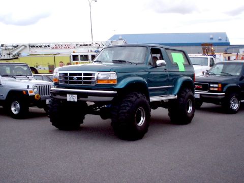
1996 Ford Bronco/
Photo
supermotors.net/registry/media/183524
Ford Steering Knuckle & Wheel Bearings Exploded Diagram - Fig. 255 Parts Legend

Exploded parts drawing of a steering knuckle and wheel bearing assembly with a numbered component legend.
This document is an exploded parts diagram labeled 'FIG. 255—STEERING KNUCKLE AND WHEEL BEARINGS,' apparently taken from a Ford shop or service manual (figure reference number 10554). The illustration shows the disassembled components of a front steering knuckle and wheel bearing assembly for a four-wheel-drive front axle, with each part identified by a callout number keyed to a 24-item legend. Components identified include the bearing adjusting nut, lockwashers, bearing cones and rollers, bearing caps and cups, the spindle, bushing, filler plug, the left knuckle and arm, adjustment shims, upper and lower bearing caps with their bolts and lockwashers, oil seal and backing ring, thrust washer, axle pilot, multiple oil seals, seal retainer, and retaining bolts. A reader can learn the correct order and relationship of parts when disassembling or reassembling the steering knuckle and front wheel bearings, including where the shims, seals, and thrust washer are positioned relative to the knuckle and spindle. No torque specifications, part numbers, model years, or written service procedures are included—only the exploded view and part-name legend.
Is this accurate? Sign in to help verify it.
Frequently asked questions
- What parts are shown in this steering knuckle and wheel bearing diagram?
- The legend lists 24 parts: bearing adjusting nut, lockwashers, bearing cone and rollers, bearing cap, spindle, bushing, filler plug, left knuckle and arm, shims, upper bearing cap, bolts, oil seal and backing ring, thrust washer, axle pilot, oil seals, bearing cup, another bearing cone and rollers, retainer, and lower bearing cap.
- Which callout number is the spindle?
- The spindle is item 6 in the legend.
- Where are the shims located in the assembly?
- The shims are item 10, shown at the upper bearing cap area of the knuckle, beneath the upper bearing cap (item 11), its lockwasher (12), and bolt (13).
- What is item 14 in the diagram?
- Item 14 is the Oil Seal and Backing Ring.
- Does this diagram include torque specs or part numbers?
- No. It only shows an exploded view with a numbered legend of part names; no torque values or Ford part numbers are given. The only reference number visible is the figure ID 10554.
Comments
More from this build




No comments yet.