Home/
Registry/
Ford/
Bronco/
1987-1991/
1988 Ford Bronco/
Photo
supermotors.net/registry/media/253542
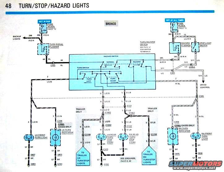
Ford Bronco Turn Signal, Stop & Hazard Lights Wiring Diagram (Page 48)
Reference · 1987-1991 BroncoAll 175 wiring diagrams




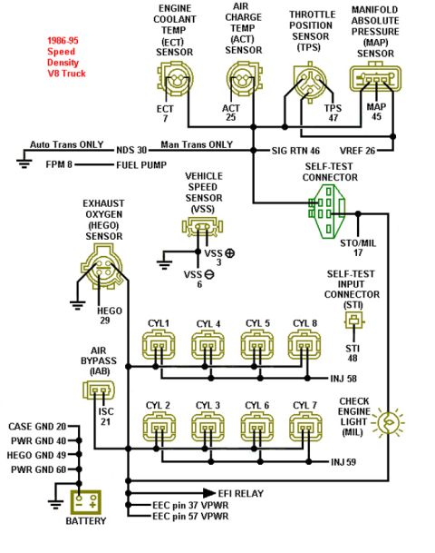
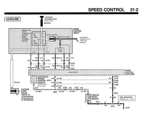
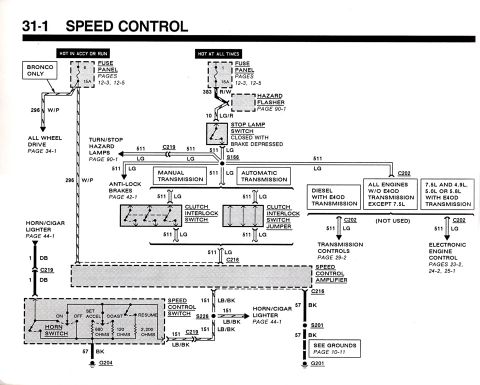
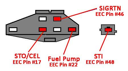
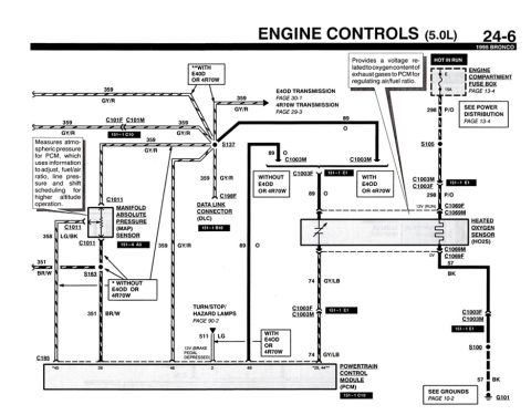










Wiring diagram of the Bronco turn, stop, and hazard light system, showing the turn signal flasher, hazard switch, stop light switch, and trailer light circuits.
Part of 1987-1991 Ford Bronco Wiring Diagrams
This document is page 48 of a Ford factory-style electrical wiring diagram covering the Turn, Stop, and Hazard light circuits for the Bronco. It shows power feeds from the fuse block (page 15): a 15A 'Hot in Run' fuse feeding circuit 298 (P/O) to the backup lights and turn signal flasher (which outputs circuit 44 BL), and a 15A 'Hot at All Times' fuse feeding circuit 383 (R/W) to the hazard flasher and stop light switch. The hazard flasher outputs circuit 385 (W/R) and the stop light switch outputs circuit 511 (LG), which also branches to the speed control via connector C205A. The combined turn/hazard switch (terminal details on page 97) routes power to the left side on circuit 3 (LG/W) and 9 (LG/O), and the right side on circuit 2 (W/BL) and 5 (O/LB), feeding the front turn lights, dash turn indicators (through C208/C208A, gages only), and rear turn/stop lights. Trailer-only branches through connector C1104 feed trailer turn/stop lights. All lamp grounds run on circuit 57 (BK) to grounds G801, G701, and G802 through splices S805-S808 (grounds detailed on pages 6 and 46).
Is this accurate? Sign in to help verify it.
Frequently asked questions
- What fuse powers the turn signal flasher on the Bronco?
- A 15A fuse in the fuse block (Hot in Run, fuse block details on page 15) feeds circuit 298 (P/O) to the turn signal flasher and also to the backup lights.
- What wire colors are used for the Bronco turn signal circuits?
- Left side: circuit 3 LG/W (front/indicator) and circuit 9 LG/O (rear). Right side: circuit 2 W/BL (front/indicator) and circuit 5 O/LB (rear). Grounds are circuit 57 BK.
- How is the hazard flasher powered?
- By a 15A 'Hot at All Times' fuse via circuit 383 R/W; the hazard flasher output is circuit 385 W/R, which passes through connector C305 to the hazard switch.
- Where do the turn/stop light circuits ground?
- Through circuit 57 BK wires to grounds G801 (LH front), G802 (RH front), and G701 (rear and RH indicator), via splices S805, S806, S807, and S808. Ground details are on pages 6 and 46.
- What connectors carry the trailer turn/stop light circuits?
- Trailer-only branches pass through connector C1104: circuit 9 LG/O to the trailer LH turn/stop lights and circuit 5 O/LB to the trailer RH turn/stop lights.






No comments yet.