Home/
Registry/
Ford/
Bronco/
1987-1991/
1989 Ford Bronco/
Photo
supermotors.net/registry/media/281287
Ford Bronco U-Joint Forces Diagram - Rotation, Compression & Tearing Force

Reference · 1987-1991 BroncoAll 95 service procedures
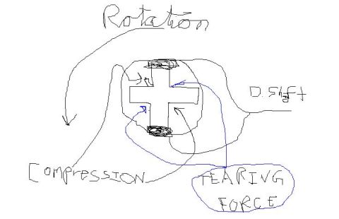




Freehand sketch annotating rotation, compression, drift, and tearing forces on a welded cross joint.
Part of 1987-1991 Ford Bronco Service Procedures
This document is a hand-drawn (digitally sketched) diagram illustrating the forces acting on a universal joint (u-joint) cross, uploaded as a service/reference sketch for a 1989 Ford Bronco. The drawing shows a u-joint cross (spider) with bearing caps sketched on the top and bottom trunnions. A large curved arrow labeled "Rotation" indicates the rotational direction of the joint, and a label "D.Shaft" identifies the driveshaft side. An arrow labeled "Compression" shows the direction of compressive loading, while blue arrows originating from a circled label reading "TEARING FORCE" point to the trunnions of the cross, indicating where tearing (tensile) stress acts on the joint during operation. The sketch contains no part numbers, torque specifications, dimensions, dates, or vehicle-specific applicability information. A reader can learn conceptually how rotation of the driveshaft translates into compression and tearing forces on the u-joint cross, which is useful background for understanding u-joint wear patterns and failure modes, though the document itself provides no procedural steps or specifications.
Is this accurate? Sign in to help verify it.
Frequently asked questions
- What forces are shown acting on the u-joint in this diagram?
- The diagram labels three things: Rotation (a large curved arrow around the u-joint cross), Compression (an arrow pointing away from the cross), and Tearing Force (blue arrows pointing at the trunnions of the cross).
- What does 'D.Shaft' refer to in the sketch?
- 'D.Shaft' labels the driveshaft side of the u-joint, indicating where the driveshaft connects relative to the cross.
- Where does the tearing force act according to the diagram?
- Blue arrows from the circled 'TEARING FORCE' label point toward the trunnions (arms) of the u-joint cross, showing that tearing stress acts on the cross arms during rotation.
- Does this document give torque specs or part numbers for u-joint service?
- No. It is purely a conceptual force diagram; no torque values, part numbers, or specifications appear.






No comments yet.