Home/
Registry/
Ford/
Bronco/
1987-1991/
1989 Ford Bronco/
Photo
supermotors.net/registry/media/288070
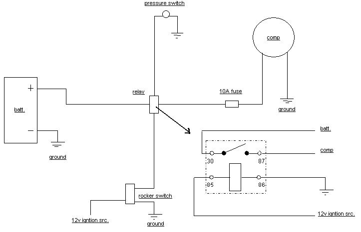
York Compressor Onboard Air Wiring Diagram - Relay, Pressure Switch & 10A Fuse
Reference · 1987-1991 BroncoAll 175 wiring diagrams
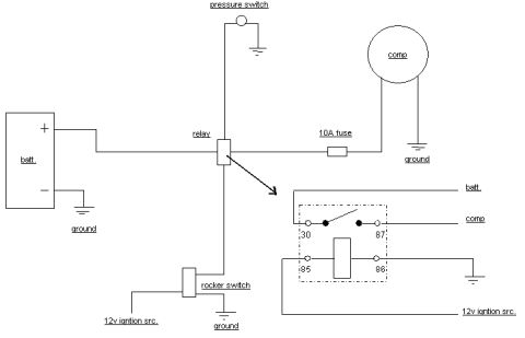


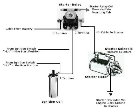
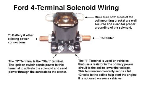

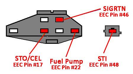
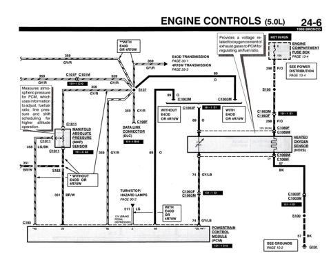
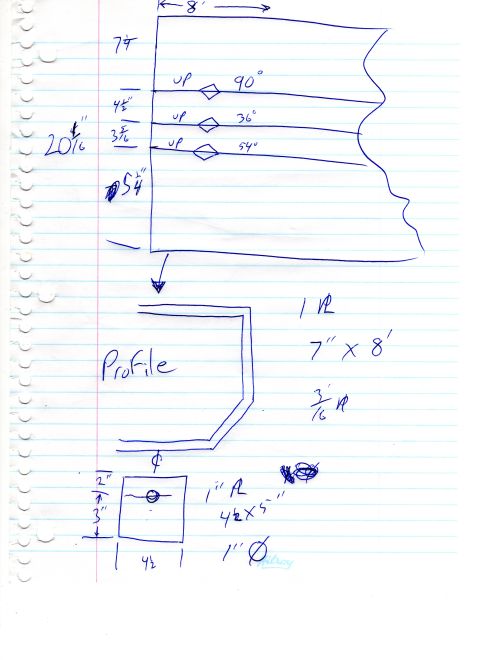







Wiring diagram showing a compressor circuit with battery, relay, 10A fuse, pressure switch, and rocker switch plus relay pinout.
Part of 1987-1991 Ford Bronco Wiring Diagrams
This document is a simple hand-drawn (computer-drafted) wiring diagram showing how to wire an air compressor (labeled 'comp') to a vehicle's 12-volt electrical system using a standard automotive relay. The battery ('batt.') positive terminal feeds the relay, and the relay's switched output passes through a 10A fuse to the compressor, which is grounded on its other side. A pressure switch, grounded on one side, ties into the relay control circuit. A rocker switch, fed by a '12v igntion src.' (12V ignition source) and grounded, provides operator control of the relay. An inset detail (indicated by an arrow from the relay symbol) shows the standard relay pinout: pin 30 connects to battery, pin 87 to the compressor, pin 85 to the switch/control circuit, and pin 86 to ground, with a 12V ignition source feeding the control side. The diagram is useful for anyone installing an onboard air compressor (such as a York-style compressor conversion, per the filename) in a truck, showing power routing, fusing, grounding points, and relay terminal assignments. No vehicle year, make, model, part numbers, or wire colors are stated in the document itself.
Is this accurate? Sign in to help verify it.
Frequently asked questions
- What size fuse does this compressor wiring diagram call for?
- A 10A fuse, placed between the relay output and the compressor.
- How are the relay pins wired in this diagram?
- Pin 30 goes to battery, pin 87 to the compressor, pin 85 to the switch/control circuit, and pin 86 to ground, with a 12V ignition source feeding the control side.
- What switches control the compressor in this setup?
- A pressure switch (grounded on one side) and a rocker switch fed by a 12V ignition source both tie into the relay control circuit.
- Where does the compressor get its ground?
- The compressor has its own ground connection on the side opposite the fused relay feed; the battery negative, rocker switch, and relay pin 86 are also grounded.
- Is the compressor powered directly from the battery?
- Battery positive feeds the relay (pin 30); the relay's switched output (pin 87) then powers the compressor through the 10A fuse.






No comments yet.