Home/
Registry/
Ford/
Bronco/
1987-1991/
1989 Ford Bronco/
Photo
supermotors.net/registry/media/257981
Ford Bronco RABS Valve & Speed Sensor Removal - Rear ABS Service Procedure
Reference · 1987-1991 BroncoAll 95 service procedures
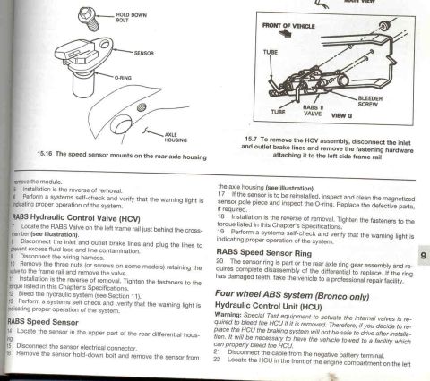








Service manual page covering RABS hydraulic control valve (HCV) on left frame rail, rear-axle speed sensor removal, sensor ring inspection, and Bronco-only 4-wheel ABS HCU warning.
Part of 1987-1991 Ford Bronco Service Procedures
This is a scanned page from a Haynes-style repair manual covering the Rear Anti-lock Brake System (RABS) and four-wheel ABS on Ford Bronco/F-Series trucks. It includes two illustrations: figure 15.16 showing the RABS speed sensor mounting on the rear axle housing (with hold-down bolt, sensor, and O-ring called out), and figure 15.7 showing the RABS II valve (HCV assembly) on the left frame rail with tubes and bleeder screw. The text provides step-by-step removal and installation procedures for the RABS Hydraulic Control Valve (HCV), located on the left frame rail behind the crossmember, including disconnecting brake lines, wiring harness, and three retaining nuts/screws, followed by bleeding the hydraulic system. It also covers the RABS speed sensor removal from the rear differential housing, inspecting the magnetized pole piece and O-ring, and notes that the RABS speed sensor ring is part of the ring gear assembly requiring complete differential disassembly. The page ends with the beginning of the four-wheel ABS Hydraulic Control Unit (HCU) procedure (Bronco only), including a warning that special test equipment is required to bleed the HCU after replacement, meaning the vehicle must be towed for proper bleeding.
Is this accurate? Sign in to help verify it.
Frequently asked questions
- Where is the RABS Hydraulic Control Valve (HCV) located?
- The RABS Valve is on the left frame rail just behind the crossmember. To remove it, disconnect the inlet and outlet brake lines, plug the lines, disconnect the wiring harness, and remove the three nuts (or screws on some models) retaining the valve to the frame rail.
- Where is the RABS speed sensor mounted?
- The sensor is located in the upper part of the rear differential housing, mounted on the rear axle housing with a hold-down bolt and sealed with an O-ring.
- Can I replace the RABS speed sensor ring myself?
- The sensor ring is part of the rear axle ring gear assembly and requires complete disassembly of the differential to replace. If the ring has damaged teeth, the manual advises taking the vehicle to a professional repair facility.
- Why can't I drive after replacing the four-wheel ABS Hydraulic Control Unit (HCU)?
- Special test equipment is required to actuate the internal valves and bleed the HCU if it is removed. If you replace the HCU, the braking system will not be safe to drive; the vehicle must be towed to a facility that can properly bleed the HCU.
- What should be checked when reinstalling the RABS speed sensor?
- Inspect and clean the magnetized sensor pole piece and inspect the O-ring, replacing defective parts if required. Tighten fasteners to the torque listed in the Chapter's Specifications and perform a systems self-check to verify the warning light indicates proper operation.






No comments yet.