Home/
Registry/
Ford/
Probe/
1993-1997/
1994 Ford Probe/
Photo
supermotors.net/registry/media/297990
1994 Ford Probe Vacuum Hose Routing Diagram - VRIS, EGR & Purge Solenoids

Reference · 1993-1997 ProbeAll 9 vacuum routing diagrams
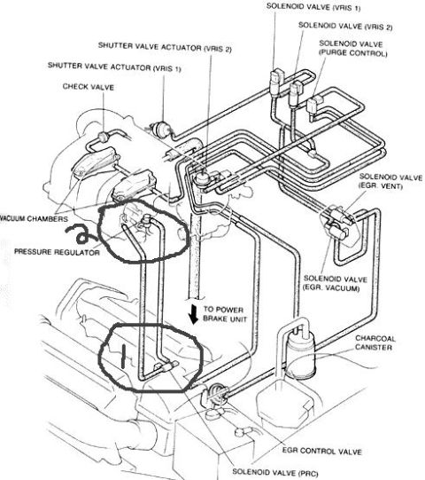
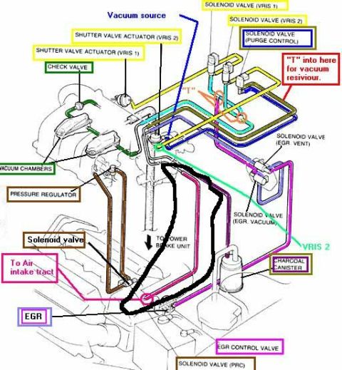
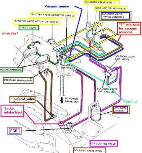
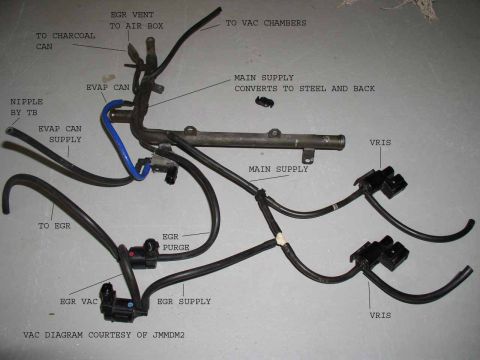

Vacuum hose routing diagram showing solenoid valves, vacuum chambers, EGR, charcoal canister, and the line to the power brake unit.
Part of 1993-1997 Ford Probe Vacuum Routing Diagrams
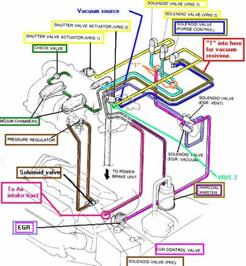
This document is a scanned engine vacuum hose routing diagram uploaded for a 1994 Ford Probe. It is a line-art illustration of the engine (viewed from above/front) showing the routing of vacuum hoses among emission and intake control components. Labeled components include the VRIS 1 and VRIS 2 solenoid valves and their corresponding shutter valve actuators, a purge control solenoid valve, a check valve, vacuum chambers, the fuel pressure regulator, EGR vent and EGR vacuum solenoid valves, the EGR control valve, the PRC solenoid valve, the charcoal canister, and a hose leading to the power brake unit (brake booster). Two areas of the diagram, around the pressure regulator/vacuum chambers and a hose junction lower on the engine, are circled by hand in marker, apparently to highlight components or connections of interest to the uploader. The diagram contains no visible year, model, engine code, part numbers, or torque values; it consists solely of the illustration and component callout labels. A reader can use it to identify where each vacuum line connects between the intake manifold area, emission solenoids, EGR system, canister, and brake booster.
Is this accurate? Sign in to help verify it.
Frequently asked questions
- What solenoid valves are shown on this vacuum diagram?
- The diagram labels solenoid valves for VRIS 1, VRIS 2, purge control, EGR vent, EGR vacuum, and PRC.
- Does the diagram show where the brake booster vacuum line connects?
- Yes, an arrow labeled 'TO POWER BRAKE UNIT' indicates the hose that runs to the power brake unit.
- What VRIS components are identified?
- It shows the shutter valve actuators for VRIS 1 and VRIS 2 along with their respective solenoid valves (VRIS 1 and VRIS 2).
- What EGR components appear in the diagram?
- The EGR control valve, the EGR vent solenoid valve, and the EGR vacuum solenoid valve are all labeled.
- Are the fuel pressure regulator and charcoal canister shown?
- Yes, both the pressure regulator (near the circled vacuum chambers) and the charcoal canister are labeled on the diagram.
No comments yet.