1995 Ford Probe Vacuum Hose Routing Diagram - VRIS, EGR & Solenoid Valves
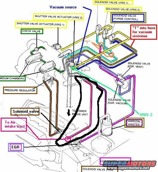
Color-coded vacuum routing diagram showing solenoid valves, EGR, charcoal canister and shutter valve actuators (VRIS).
This document is an annotated engine vacuum routing diagram, uploaded for a 1995 Ford Probe. It is a line drawing of the engine's intake area with color-coded vacuum hoses and labeled callouts identifying vacuum system components. Labeled items include the vacuum source, two shutter valve actuators (VRIS 1 and VRIS 2) and their corresponding solenoid valves, a purge control solenoid valve, a check valve, vacuum chambers, the fuel pressure regulator, EGR-related components (EGR valve, EGR control valve, solenoid valves for EGR vent and EGR vacuum), a charcoal canister, a PRC solenoid valve, and a line going to the power brake unit. A red annotation instructs where to "T" into a hose for a vacuum reservoir (spelled "resiviour" in the original), and another callout notes a hose going "To Air intake tract." The diagram uses distinct colors (yellow, blue, pink/magenta, green, brown, black, cyan) to trace individual vacuum lines between components. A reader can learn the routing and connection points of the vacuum hoses for the VRIS (variable resonance induction system), EGR, evaporative emissions (purge/charcoal canister), fuel pressure regulator, and brake booster circuits on this engine. No year, engine size, or part numbers are stated on the document itself.
Is this accurate? Sign in to help verify it.
Frequently asked questions
- What VRIS components are shown on this vacuum diagram?
- It shows the Shutter Valve Actuator (VRIS 1), Shutter Valve Actuator (VRIS 2), Solenoid Valve (VRIS 1), and Solenoid Valve (VRIS 2), with the vacuum lines connecting them.
- Which EGR components are labeled in the diagram?
- The EGR valve, EGR Control Valve, Solenoid Valve (EGR. Vent), and Solenoid Valve (EGR. Vacuum) are all labeled.
- Where does the diagram say to tap in for a vacuum reservoir?
- A red callout points to a specific hose with the note "'T' into here for vacuum resiviour," indicating where to tee into the line.
- Does the diagram show the brake booster vacuum connection?
- Yes, a hose is labeled "TO POWER BRAKE UNIT," showing where the power brake vacuum line connects.
- What evaporative emissions parts appear in this diagram?
- The Solenoid Valve (Purge Control) and the Charcoal Canister are shown, along with the Solenoid Valve (PRC).
Comments
More from this build







No comments yet.