1994 Ford Probe V6 Vacuum Hose Routing Diagram - VRIS, EGR & Purge Solenoids
Reference · 1993-1997 ProbeAll 9 vacuum routing diagrams
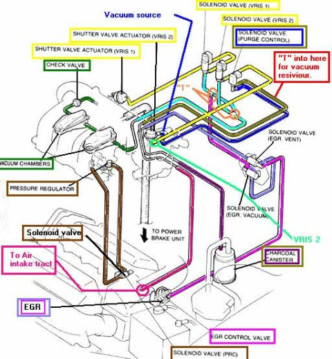
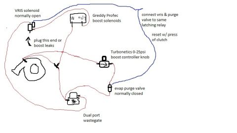
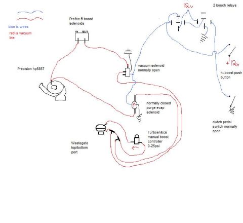
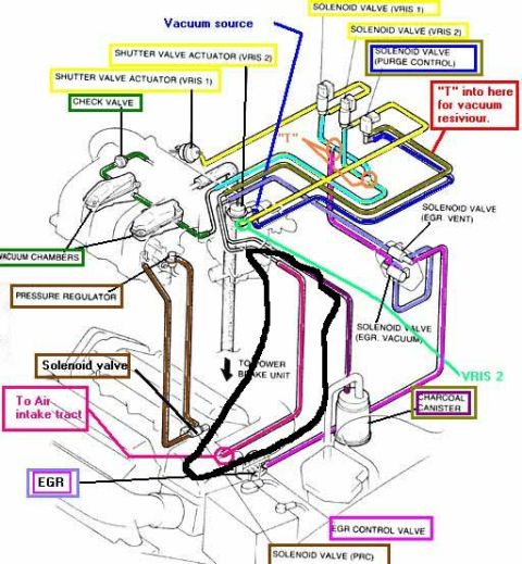
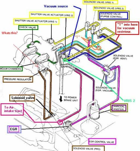
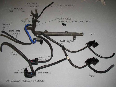
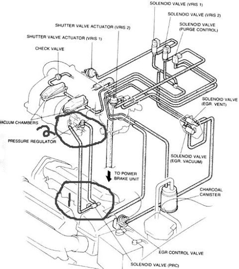







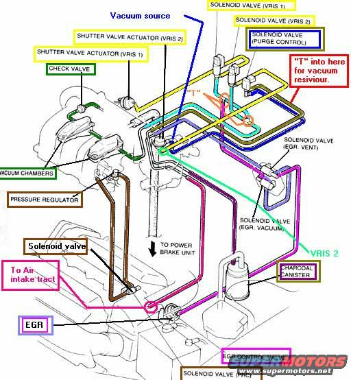
Vacuum hose routing diagram showing vacuum source, VRIS shutter valve actuators, EGR and purge solenoid valves, charcoal canister and vacuum reservoir.
Part of 1993-1997 Ford Probe Vacuum Routing Diagrams
This document is a color-coded vacuum hose routing diagram for an automotive engine, uploaded as applying to a 1994 Ford Probe. The diagram shows an isometric illustration of the engine's intake manifold and vacuum system with individual hoses traced in distinct colors, each identified by a callout label. Components labeled include the vacuum source, two shutter valve actuators (VRIS 1 and VRIS 2) with their corresponding solenoid valves, a check valve, vacuum chambers, the fuel pressure regulator, a purge control solenoid valve, EGR vent and EGR vacuum solenoid valves, the EGR valve and EGR control valve, a PRC solenoid valve, the charcoal canister, and a line to the power brake unit. Annotations indicate a "T" fitting location for tapping vacuum for a vacuum reservoir ("'T' into here for vacuum resiviour"), a connection "To Air intake tract," and identification of the VRIS 2 hose run. A reader can use this diagram to trace and correctly reconnect every vacuum hose in the system, identify the location of each solenoid valve and actuator, and locate suitable points to tap vacuum. The document itself contains no year, make, model, or part number text.
Is this accurate? Sign in to help verify it.
Frequently asked questions
- Where can I tap into the vacuum system for a vacuum reservoir?
- The diagram marks a red callout reading "'T' into here for vacuum resiviour," pointing to a specific hose junction on the right side of the manifold where a T-fitting can be added.
- What solenoid valves are shown in this vacuum diagram?
- Solenoid valves for VRIS 1, VRIS 2, purge control, EGR vent, EGR vacuum, and PRC are labeled, plus an additional unlabeled 'Solenoid valve' callout near the lower left.
- What operates the VRIS shutter valves?
- Each shutter valve actuator (VRIS 1 and VRIS 2) is connected via vacuum hoses to its own solenoid valve (SOLENOID VALVE VRIS 1 and SOLENOID VALVE VRIS 2), supplied from the vacuum source and vacuum chambers with a check valve in the circuit.
- Where does the power brake booster get its vacuum?
- A hose labeled "TO POWER BRAKE UNIT" runs from the center of the manifold area downward, as indicated by the black arrow in the diagram.
- What emissions components are included in the routing?
- The diagram shows the EGR valve, EGR control valve, EGR vent and EGR vacuum solenoid valves, the charcoal canister, and the purge control solenoid valve.






No comments yet.