1995 Ford Probe Multi-Stage Boost Control Vacuum & Wiring Diagram - Profec B
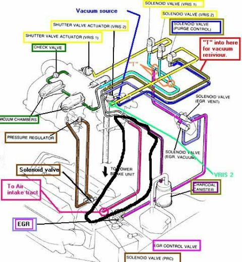
Reference · 1993-1997 ProbeAll 9 vacuum routing diagrams
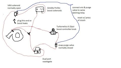
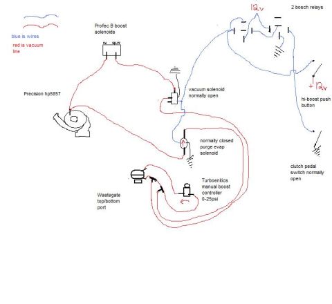





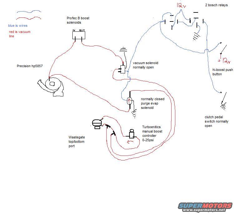
Hand-drawn boost-control schematic: Precision HP5857 turbo, Profec B boost solenoids, vacuum/purge solenoids, Turbonetics 0-25psi manual boost controller, with blue wires and red vacuum lines, 12V relays, hi-boost button.
Part of 1993-1997 Ford Probe Vacuum Routing Diagrams
This is a hand-drawn (computer-sketched) vacuum routing and wiring diagram showing a custom multi-stage turbo boost control setup, uploaded to a 1995 Ford Probe gallery. A legend indicates blue lines are electrical wires and red lines are vacuum lines. Components shown include a Profec B boost solenoid assembly (with IN and OUT ports), a Precision hp5857 turbocharger, a normally-open vacuum solenoid, a normally-closed purge/EVAP solenoid, a Turbonetics ('Turboenitics') manual boost controller rated 0-25 psi, and the wastegate top/bottom ports. Electrical control is provided by two Bosch relays fed 12V, a hi-boost push button (also fed +12V), and a normally-open clutch pedal switch. The red vacuum lines route boost pressure from the turbo compressor through the Profec B solenoids, the vacuum solenoid, the purge solenoid, and the manual boost controller to the wastegate ports, allowing switching between boost levels. The blue wiring shows the relays energizing the solenoids via the push button and clutch pedal switch. A reader can learn how this owner plumbed and wired a switchable high/low boost system combining an electronic boost controller solenoid with a manual boost controller.
Is this accurate? Sign in to help verify it.
Frequently asked questions
- What turbocharger is used in this boost setup?
- The diagram labels the turbo as a Precision hp5857.
- What do the blue and red lines mean in the diagram?
- Per the legend, blue lines are wires and red lines are vacuum line.
- What manual boost controller is shown and what is its range?
- A Turbonetics ('Turboenitics') manual boost controller rated 0-25 psi.
- How is the hi-boost mode triggered electrically?
- Through two Bosch relays fed 12V, controlled by a hi-boost push button (+12V) and a normally-open clutch pedal switch.
- What solenoids are used in the vacuum routing?
- Profec B boost solenoids (IN/OUT), a normally-open vacuum solenoid, and a normally-closed purge EVAP solenoid, routing to the wastegate top/bottom ports.






No comments yet.