Home/
Registry/
Ford/
Probe/
1993-1997/
“Red Headed Bastard Stepchild Of Ford”/
Photo
supermotors.net/registry/media/603617
1995 Ford Probe Vacuum Hose Routing Diagram - VRIS, EGR & Purge Solenoids
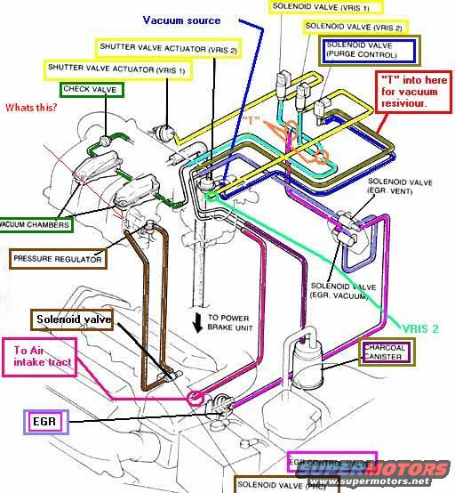
Vacuum routing diagram showing color-coded hoses between solenoid valves, EGR, vacuum source, pressure regulator and charcoal canister.
This document is an annotated (modified) vacuum hose routing diagram uploaded for a 1995 Ford Probe. It is a perspective drawing of the engine's intake manifold area with color-coded vacuum lines and callout labels identifying each vacuum component. Labeled components include the vacuum source, two VRIS solenoid valves (VRIS 1 and VRIS 2) and their corresponding shutter valve actuators, a purge control solenoid valve, a check valve, vacuum chambers, the fuel pressure regulator, EGR-related components (solenoid valve for EGR vent, solenoid valve for EGR vacuum, the EGR valve itself, the EGR control valve, and the PRC solenoid valve), the charcoal canister, and a line running to the power brake unit. Handwritten-style annotations added by the uploader include "Whats this?" pointing to an unidentified item, a "T" marker with the note "'T' into here for vacuum resiviour" (reservoir), a generic "Solenoid valve" label, and "To Air intake tract." A reader can learn the routing of each vacuum hose, which solenoid controls which actuator (VRIS, EGR, purge), and where to tee in a vacuum reservoir for a modification. The document contains no part numbers, year statements, or torque/fuse data.
Is this accurate? Sign in to help verify it.
Frequently asked questions
- Where does the diagram say to tee in a vacuum reservoir?
- An annotation reading "'T' into here for vacuum resiviour" points to a marked "T" location on the vacuum line near the solenoid valves at the top rear of the manifold.
- What EGR-related components are shown in this vacuum diagram?
- It labels the EGR valve, the EGR control valve, a solenoid valve (EGR vent), a solenoid valve (EGR vacuum), and a solenoid valve (PRC).
- What controls the VRIS shutter valve actuators?
- The diagram shows Solenoid Valve (VRIS 1) and Solenoid Valve (VRIS 2) connected to Shutter Valve Actuator (VRIS 1) and Shutter Valve Actuator (VRIS 2) respectively.
- Where does one of the main vacuum lines route besides the engine components?
- One line is labeled "TO POWER BRAKE UNIT," another goes "To Air intake tract," and a hose connects to the charcoal canister via the purge control solenoid valve.
- Does the diagram identify a check valve and vacuum chambers?
- Yes, a check valve is labeled on the driver-side vacuum line and two vacuum chambers are labeled on the intake manifold area.
Comments
More from this build




No comments yet.