Ford Bronco A/C Condenser Assembly 19C600 Installation & Hose Routing Diagram

Reference · 1978-1979 BroncoAll 16 vacuum routing diagrams
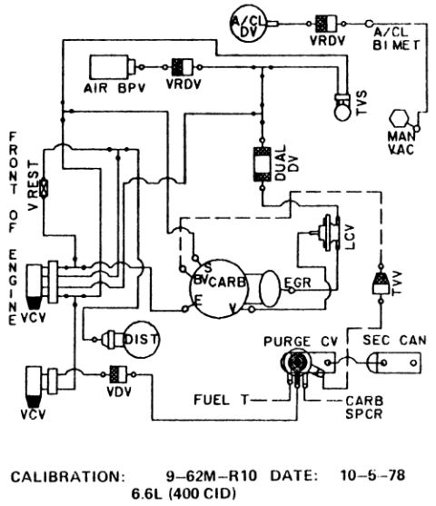
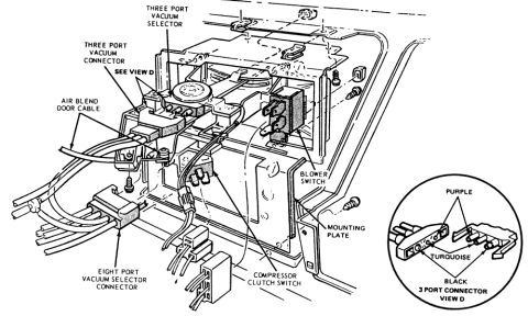
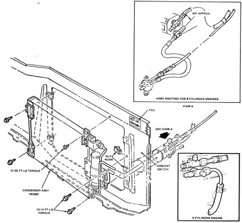
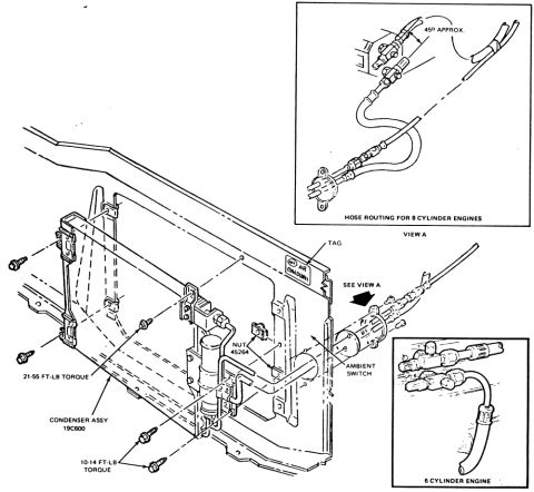
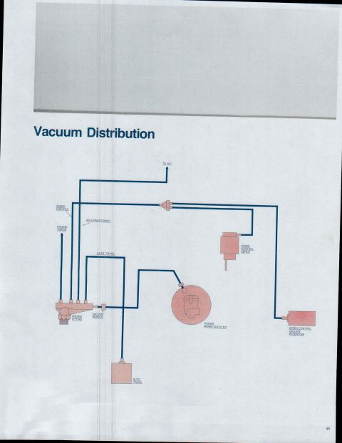
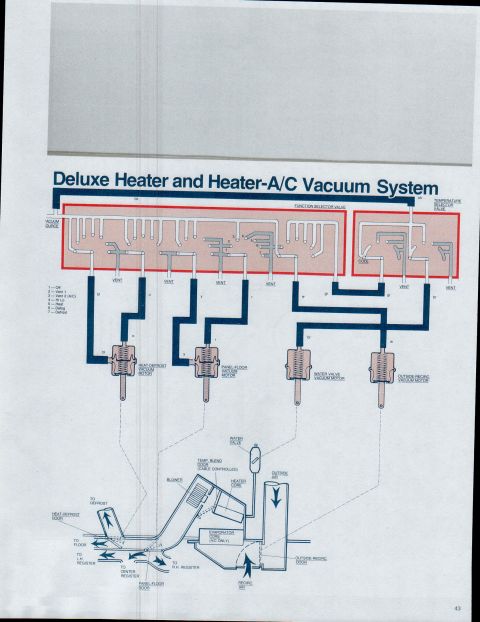
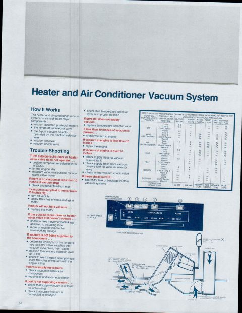
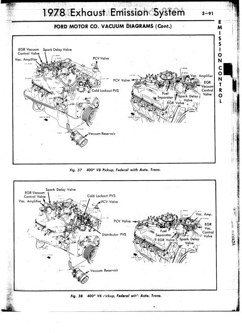
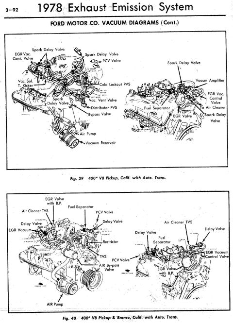
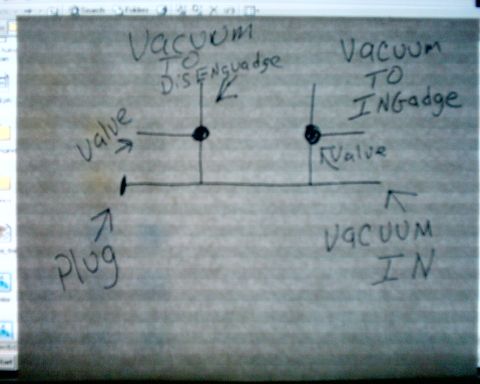
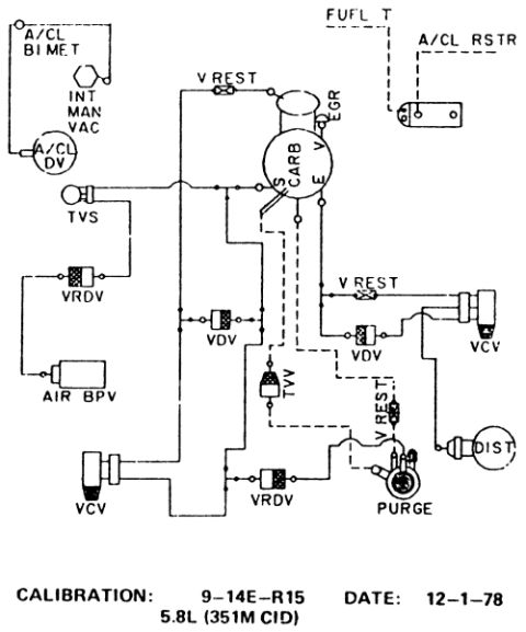
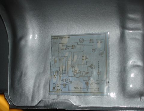




A/C condenser assembly (19C600) exploded view with mounting torque specs plus vacuum/ambient-switch hose routing for 8-cylinder and 6-cylinder engines (View A).
Part of 1978-1979 Ford Bronco Vacuum Routing Diagrams
This document is an exploded-view illustration showing the installation of an air conditioning condenser assembly (part reference 19C600) at the front of a Ford truck/Bronco radiator support. The main drawing shows the condenser assembly with its mounting brackets and screws, along with two torque specifications: 21-55 ft-lb torque for the larger fasteners and 10-14 ft-lb torque for the smaller mounting screws. Callouts identify the ambient switch, a nut (45264), and an air conditioning identification tag on the radiator support panel. An arrow labeled "SEE VIEW A" directs the reader to an inset drawing in the upper right titled "HOSE ROUTING FOR 8 CYLINDER ENGINES (VIEW A)," which shows the refrigerant hose routing with fittings positioned at approximately 45 degrees. A second inset in the lower right, labeled "6 CYLINDER ENGINE," shows the alternate hose routing and fitting arrangement for six-cylinder applications. From this diagram, a reader can learn how the A/C condenser mounts to the radiator support, the fastener torque values required, where the ambient switch is located, and how the A/C hoses are routed differently between 8-cylinder and 6-cylinder engines.
Is this accurate? Sign in to help verify it.
Frequently asked questions
- What torque values are specified for mounting the A/C condenser?
- The diagram specifies 21-55 ft-lb torque for the larger fasteners and 10-14 ft-lb torque for the smaller mounting screws.
- What is the part reference for the condenser assembly?
- The condenser assembly is labeled with reference number 19C600.
- Does the hose routing differ between engine types?
- Yes. View A shows the hose routing for 8-cylinder engines (with fittings at approximately 45°), and a separate inset shows the routing for the 6-cylinder engine.
- Where is the ambient switch located?
- The ambient switch is shown mounted on the radiator support area near the condenser, called out in the main exploded view.
- What nut is called out in the diagram?
- A nut with the number 45264 is called out near the ambient switch mounting.






No comments yet.