Home/
Registry/
Ford/
Bronco/
1987-1991/
1988 Ford Bronco/
Photo
supermotors.net/registry/media/314367
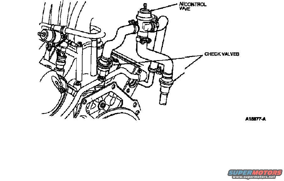
1988 Ford Bronco 5.0 Thermactor Diagram - Air Control Valve & Check Valves
Reference · 1987-1991 BroncoAll 112 schematics










Schematic line diagram identifying the air-injection control valve and check valves and their routing on the engine.
Part of 1987-1991 Ford Bronco Schematics
This document is a single line-art schematic illustration showing the Thermactor (secondary air injection) system components mounted on an engine, as filed for a 1988 Ford Bronco with a 5.0L engine. Two callouts identify parts on the drawing: an air control valve (labeled with degraded text reading "AII CONTROL VAVE") located at the top of the assembly with a vacuum diaphragm on top and hoses attached, and two check valves indicated by leader lines pointing to fittings on air tubes near the intake/exhaust area of the engine. The illustration bears the figure identification number A18877-A in the lower right corner. There is no other text, table, torque specification, or wiring information in the image. A reader can use this diagram to visually locate the air control valve and the check valves on the engine and understand their physical arrangement relative to the air hoses and hard tubes of the Thermactor emissions system. The document itself does not state a year, model, or engine applicability; that attribution comes solely from the uploader's filename.
Is this accurate? Sign in to help verify it.
Frequently asked questions
- What components are identified in this Thermactor diagram?
- Two components are labeled: the air control valve (labeled "AII CONTROL VAVE" in the degraded scan) and the check valves.
- How many check valves does the diagram indicate?
- The single "CHECK VALVES" callout has leader lines pointing to two locations on the air tubes, indicating two check valves.
- Where is the air control valve located in the illustration?
- It is shown at the top of the assembly, with a vacuum diaphragm on top and hoses connected on either side, above the check valves.
- What is the figure reference number on this diagram?
- The illustration is marked A18877-A in the lower right corner.






No comments yet.