Home/
Registry/
Ford/
Bronco/
1987-1991/
1988 Ford Bronco/
Photo
supermotors.net/registry/media/465077
1992 Ford 5.0L/5.8L Engine Bay Component Connector Locations Diagram

Reference · 1987-1991 BroncoAll 110 schematics
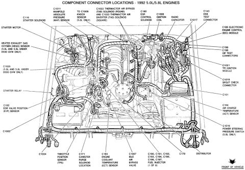
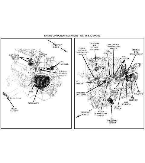
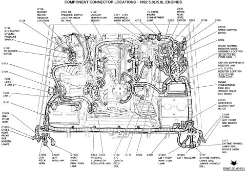



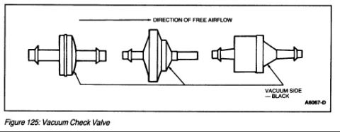


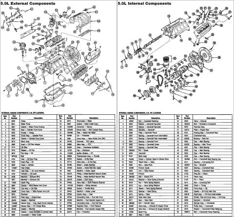






Ford engine-compartment component/connector-location diagram for 1992 5.0L/5.8L engines, mapping connectors (C-numbers), ground points (G-numbers), sensors, relays and the engine-compartment fuse box.
Part of 1987-1991 Ford Bronco Schematics
This document is a component connector location diagram for 1992 Ford 5.0L/5.8L engines, showing an overhead line-art view of the engine compartment with the front of the vehicle indicated at the bottom right. Numbered callouts identify the physical locations of electrical connectors, grounds, and fuse links throughout the engine bay. Identified items include the blower motor resistor (C169), oil pressure switch (C135, near the oil pan), coolant temperature sender (C150), windshield wiper motor (C151/C152), engine compartment lamp feed (to C1035), brake fluid level switch (C170), speed control servo (C1018), windshield washer pump motor (C1030), A/C clutch field coil (C163), integral alternator regulator (IAR, C153/C154), horns (C1005 low pitch, C1006 high pitch), headlamps (C1033, C1034), park/turn lamps (C1031, C1032), side marker lamps (C1052-C1055), and the daytime running lamps (DRL) module or jumper at C177. It also locates grounds G100, G101, G103, and G104, fuse links A, B, and J, the engine compartment fuse box (with trailer relay box inside), the brake warning resistor/diode assembly (20 cm / 7.9 in from C202), and the ignition suppression and A/C clutch resistors (6 cm / 2.4 in from C101). Useful for tracing engine-bay wiring and locating connectors during electrical diagnosis.
Is this accurate? Sign in to help verify it.
Frequently asked questions
- Where is the oil pressure switch connector (C135) located on the 1992 5.0L/5.8L engine?
- The diagram shows C135, the oil pressure switch connector, located near the oil pan.
- Where is the brake warning resistor/diode assembly located?
- Per the diagram, the brake warning resistor/diode assembly is located 20 cm (7.9 in) from connector C202.
- Where are the ignition suppression resistor and A/C clutch resistor located?
- They are located 6 cm (2.4 in) from connector C101, per the diagram.
- What connectors serve the horns on this engine?
- C1005 is the low pitch horn connector and C1006 is the high pitch horn connector.
- What is inside the engine compartment fuse box according to this diagram?
- The diagram notes that the trailer relay box is inside the engine compartment fuse box.






No comments yet.