Home/
Registry/
Ford/
Bronco/
1987-1991/
1988 Ford Bronco/
Photo
supermotors.net/registry/media/465078
1987-88 Ford 5.0L Engine Component Locations Diagram - Sensors & Solenoids

Reference · 1987-1991 BroncoAll 110 schematics
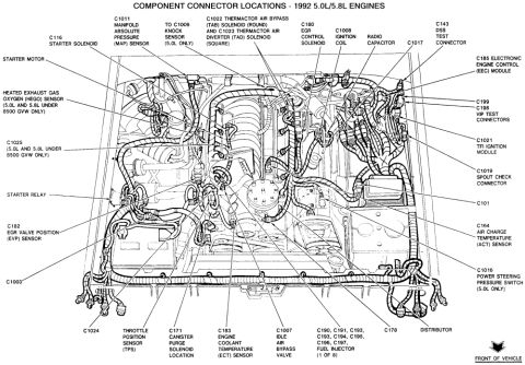
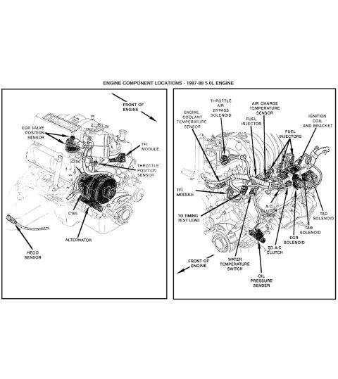
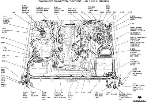



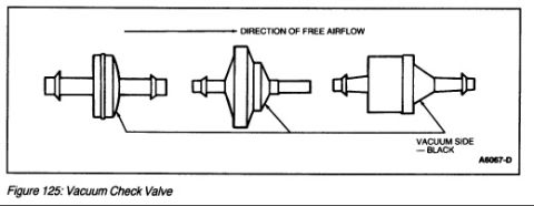


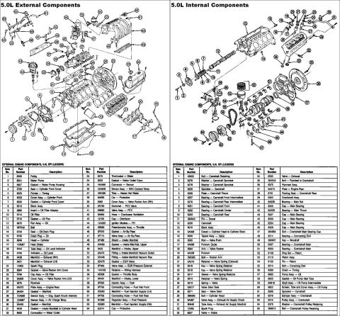






Component location schematic for a 1987-88 5.0L engine labeling sensors, TFI module, solenoids, injectors and ignition coil.
Part of 1987-1991 Ford Bronco Schematics
This document is a two-panel schematic showing engine component locations for the 1987-88 Ford 5.0L engine. The left illustration is a side view of the engine identifying the EGR valve position sensor, TFI module, throttle position sensor, alternator, HEGO (oxygen) sensor, and two connector references (C185 and C286), with an arrow indicating the front of the engine. The right illustration is a front/top perspective view of the engine and its wiring harness, identifying the throttle air bypass solenoid, air charge temperature sensor, engine coolant temperature sensor, fuel injectors, ignition coil and bracket, TFI module, timing test lead connection, A/C clutch diode, TAD solenoid, TAB solenoid, EGR solenoid, A/C clutch lead, water temperature switch, and oil pressure sender. A reader can use this diagram to physically locate sensors, solenoids, and ignition/EFI components on a 1987-1988 Ford 5.0L (302) engine for diagnosis or repair, including where to find the timing test lead and key harness connectors.
Is this accurate? Sign in to help verify it.
Frequently asked questions
- What engine and years does this component location diagram cover?
- The document is titled "Engine Component Locations - 1987-88 5.0L Engine," covering the Ford 5.0L engine for 1987-1988.
- Where is the TFI module located on the 1987-88 5.0L engine?
- The TFI module is called out in both views: on the side view it is shown near the distributor at the upper rear area of the engine, and it is also labeled on the front view near the harness on the driver's side.
- What sensors are identified in this diagram?
- The diagram identifies the EGR valve position sensor, throttle position sensor, HEGO sensor, engine coolant temperature sensor, air charge temperature sensor, water temperature switch, and oil pressure sender.
- What solenoids are shown on the 1987-88 5.0L engine?
- The throttle air bypass solenoid, TAD solenoid, TAB solenoid, and EGR solenoid are all labeled on the front-view diagram.
- Are any connector numbers identified in the diagram?
- Yes, connectors C185 and C286 are labeled on the side-view illustration.






No comments yet.