Fog/Driving Light Wiring Diagram with Bosch Relay, 20A Fuse & SPST Switch
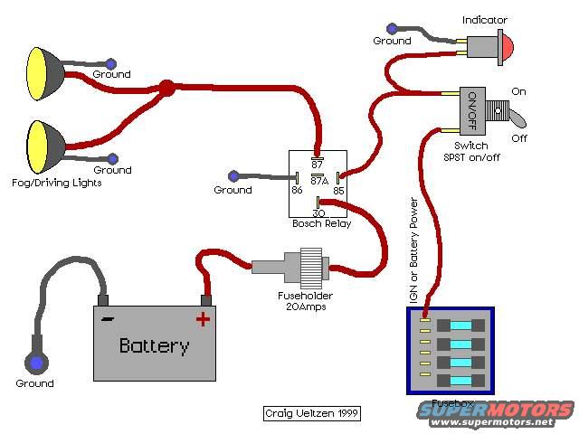
Fog and driving-light wiring diagram showing a Bosch relay, fuseholder, on/off switch, indicator and battery connections.
Part of 1992-1996 Ford Bronco Wiring Diagrams
This document is a simple color-coded wiring diagram (credited to Craig Ueltzen, 1999) showing how to wire aftermarket fog or driving lights using a standard Bosch-style relay. Power flows from the vehicle battery's positive terminal through an inline 20-amp fuseholder to relay terminal 30. Relay terminal 87 feeds the two fog/driving lights, each of which is individually grounded. Relay terminal 86 is grounded, and terminal 85 receives switched power from a SPST on/off toggle switch, which is fed by ignition or battery power drawn from the vehicle fusebox. A dash indicator lamp is wired off the switched circuit and grounded separately, so it illuminates when the lights are on. The battery negative terminal is shown grounded. The diagram identifies all five relay terminals (30, 85, 86, 87, 87A), specifies the 20-amp fuse rating, and labels every ground point. It is a generic installation reference not tied to any specific vehicle make, model, or year, making it applicable to most 12-volt vehicles including the uploader's 1995 Ford Bronco. Readers can learn the correct relay pinout, fuse sizing, switch placement, and grounding scheme for adding auxiliary fog or driving lights.
Is this accurate? Sign in to help verify it.
Frequently asked questions
- What size fuse does this fog light wiring diagram call for?
- An inline fuseholder rated at 20 amps, placed between the battery positive terminal and relay terminal 30.
- How is the Bosch relay wired in this diagram?
- Terminal 30 gets fused battery power, terminal 87 feeds the fog/driving lights, terminal 86 is grounded, and terminal 85 receives switched power from the SPST on/off switch. Terminal 87A is shown but unused.
- What kind of switch is used to control the fog lights?
- A SPST (single pole, single throw) on/off toggle switch, fed by ignition or battery power from the fusebox.
- How is the indicator light connected?
- The indicator is wired off the switched circuit between the switch and relay terminal 85, with its own ground.
- Where does the switch get its power from?
- From the vehicle fusebox, using either ignition-switched or constant battery power ('IGN or Battery Power').
Comments
More from this build






No comments yet.