Ford Bronco Ignition Switch & Starter Relay Wiring Diagram - Wire Colors, C100

Reference · 1987-1991 BroncoAll 175 wiring diagrams




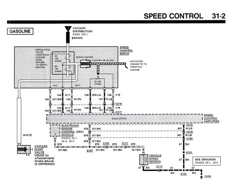
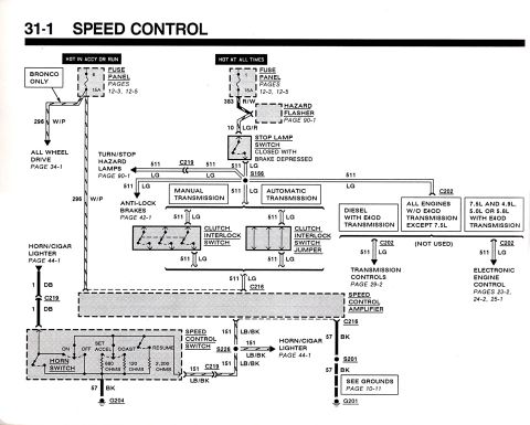
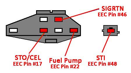
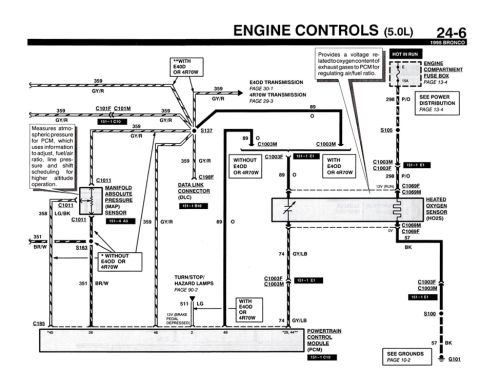










Wiring diagram showing ignition switch, starter relay and related circuits with color-coded wire labels.
Part of 1987-1991 Ford Bronco Wiring Diagrams
This document is a screen capture (Adobe Reader 7.0) of one page of a Ford truck ignition switch and starting-circuit wiring diagram, spanning schematic grid columns 16-18, rows A-B. It shows the starter relay and distributor feeds (RED-LT BLU), the clutch interlock switch used with manual transmissions (M/T), and the neutral safety/transmission range switch (positions P, R, N, D, 2, 1) for automatic transmissions (A/T). The ignition switch internal contact detail is drawn with positions ACCY, LOCK, OFF, RUN, and START, and its connector pins are labeled A2 (GRY-YEL), ST (RED-LT BLU), I1 (RED-LT GRN), A1 (BLK-LT GRN), I2 (BRN-PNK), and P2. Power comes in through BRN and BLU fusible links via connector C100 on YEL wires. Branch circuits are labeled for rear defog, back-up lights, electric shift control (RED-WHT/BLK-PNK), hazard flasher, HEGO sensor, injection blower relay, ECA power, instrument cluster, warning circuits, glow plugs (diesel), windshield wiper, cruise control (WHT-PPL), and tailgate window (BLK-WHT). Engine-specific branches are noted for (GAS), (DIESEL), and (4.9L). Two 15-amp fuses are shown (#1 15A and #4 15A). Wire colors are given throughout, useful for tracing starter and ignition-switch circuits.
Is this accurate? Sign in to help verify it.
Frequently asked questions
- What wire color goes from the ignition switch to the starter relay?
- The starter relay and distributor circuits are shown on RED-LT BLU wires, fed from the ignition switch ST terminal (RED-LT BLU) through the clutch interlock switch (M/T) or neutral safety switch (A/T).
- What are the ignition switch connector pins and wire colors?
- A2 = GRY-YEL, ST = RED-LT BLU, I1 = RED-LT GRN, A1 = BLK-LT GRN, I2 = BRN-PNK, and P2 (shown feeding a DIESEL branch).
- What ignition switch positions are shown in the diagram?
- The switch detail shows ACCY, LOCK, OFF, RUN, and START positions across the internal contacts.
- How does battery power reach the ignition switch?
- Through a BRN fusible link and a BLU fusible link on YEL wires passing through connector C100.
- What fuses appear in this diagram?
- Fuse #1 (15A), fed via the hazard flasher circuit on a RED-WHT wire, and fuse #4 (15A) on a TAN-WHT wire.





No comments yet.