Home/
Registry/
Ford/
Bronco/
1987-1991/
1990 Ford Bronco/
Photo
supermotors.net/registry/media/473125
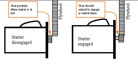
Starter Drive Gear & Flywheel Engagement Diagram - Engaged vs Disengaged
Reference · 1987-1991 BroncoAll 111 schematics
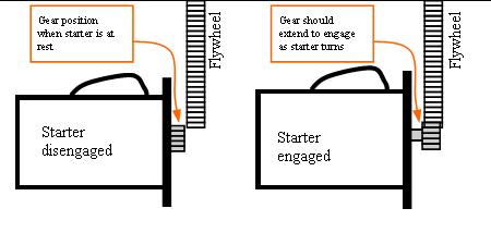




Explanatory schematic showing the starter drive gear disengaged versus engaged with the flywheel.
Part of 1987-1991 Ford Bronco Schematics
This is a simple hand-drawn schematic illustrating how a starter motor's drive gear (pinion) interacts with the engine flywheel in two states. The left diagram, labeled 'Starter disengaged,' shows the gear position when the starter is at rest, the small drive gear sits retracted, not meshed with the toothed flywheel ring. The right diagram, labeled 'Starter engaged,' shows that the 'gear should extend to engage as starter turns,' with the pinion moved outward along the starter shaft to mesh with the flywheel teeth. Orange arrows in callout boxes point to the pinion gear position in each state. The document contains no part numbers, torque specifications, wire colors, or vehicle-specific applicability information; it is a generic conceptual diagram useful for understanding or diagnosing starter drive engagement, for example, verifying that the starter drive gear extends properly to mesh with the flywheel during cranking. It was uploaded to a 1990 Ford Bronco gallery, but nothing in the drawing itself ties it to a specific year, make, or model.
Is this accurate? Sign in to help verify it.
Frequently asked questions
- What does this diagram show?
- It shows two states of a starter motor: 'Starter disengaged,' where the gear is at rest and retracted from the flywheel, and 'Starter engaged,' where the gear extends to mesh with the flywheel.
- Where should the starter gear be when the starter is at rest?
- The diagram labels the retracted position as the 'Gear position when starter is at rest', the pinion is not meshed with the flywheel.
- What should the starter gear do when the starter turns?
- Per the callout, the 'Gear should extend to engage as starter turns,' meshing with the flywheel teeth.
- Does this document specify a vehicle or part numbers?
- No. It is a generic diagram with no year, model, or part number information visible.






No comments yet.