Home/
Registry/
Ford/
Bronco/
1987-1991/
1990 Ford Bronco/
Photo
supermotors.net/registry/media/569419
How to Find TDC for Distributor Installation - Ford Firing Order & Valve Overlap

Reference · 1987-1991 BroncoAll 95 service procedures
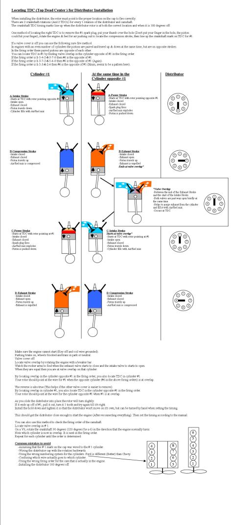






Step-by-step service instructions for locating TDC for distributor installation, with cylinder-stroke and distributor figures.
Part of 1987-1991 Ford Bronco Service Procedures
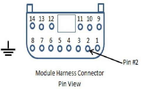
This document is an illustrated tutorial on locating Top Dead Center (TDC) for distributor installation on an engine. It explains that the crankshaft makes two rotations (and passes two TDCs) for each rotation of the distributor and camshaft, so timing marks align both when the rotor is correctly positioned and when it is 180 degrees off. It describes two methods: feeling for compression at the #1 spark plug hole with a thumb, and a 'sure fire' valve-overlap method, finding valve overlap in the cylinder opposite #1 in the firing order (#6 in the firing orders 1-5-4-2-6-3-7-8, 1-3-7-2-6-5-4-8, and 1-5-3-6-2-4). Color-coded diagrams show all four strokes (intake, compression, power, exhaust) side by side for cylinder #1 and its opposite cylinder, along with the corresponding distributor rotor position at each stage, and an inset explaining valve overlap. Step-by-step safety and procedure notes follow (ground the coil wire, set the brake, rotate with a breaker bar, watch rocker arms). It also explains how to use the method to verify camshaft firing order (rotate crank 90° for a V8, 120° for a six) and lists common mistakes such as installing the distributor 180 degrees off or using Chevy-style cylinder numbering on a Ford. Cylinder numbering diagrams for a V8 and an inline six are included.
Is this accurate? Sign in to help verify it.
Frequently asked questions
- Why do the crankshaft timing marks line up twice per distributor rotation?
- There are 2 crankshaft rotations (and 2 TDCs) for every 1 rotation of the distributor and camshaft, so the TDC marks line up both when the rotor is at the correct location and when it is 180 degrees off.
- Which cylinder is opposite #1 in common Ford firing orders?
- For firing orders 1-5-4-2-6-3-7-8, 1-3-7-2-6-5-4-8, and the six-cylinder 1-5-3-6-2-4, cylinder #6 is the opposite of #1.
- How do I find TDC on #1 using valve overlap?
- With a valve cover off, rotate the engine with a breaker bar and watch the rocker arms of the cylinder opposite #1. When the exhaust valve is closing and the intake valve is opening equally, that cylinder is at valve overlap, which means cylinder #1 is at TDC on its compression/power stroke and the rotor should point at the #1 wire.
- What is valve overlap?
- It occurs between the end of the exhaust stroke and the start of the intake stroke, when both valves are briefly part-way open at the same time. It helps purge exhaust from the cylinder and fill it with air/fuel mix, and it occurs at TDC.
- How can I check the camshaft's firing order with this method?
- Locate valve overlap in #1, then rotate the crankshaft 90 degrees for a V8 (120 degrees for a 6) in the normal direction of rotation. The cylinder now in overlap is next in the firing order; repeat until the whole order is determined.
- What common mistakes should I avoid when installing a distributor?
- Assuming the #1 mark on the cap was wired to the #1 cylinder, wiring the cap with rotation backwards, using the wrong cylinder numbering system (Ford differs from Chevy), confusing which wire goes to which cylinder, using the wrong firing order for the installed cam, and installing the distributor 180 degrees off.






No comments yet.