Home/
Registry/
Ford/
Bronco/
1987-1991/
1990 Ford Bronco/
Photo
supermotors.net/registry/media/756965
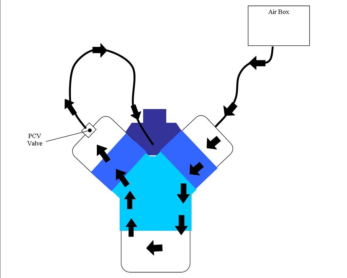
Ford Bronco PCV System Airflow Diagram - Crankcase Ventilation Flow Schematic
Reference · 1987-1991 BroncoAll 112 schematics













Schematic of PCV/crankcase ventilation airflow on a V engine with air box, PCV valve and flow arrows.
Part of 1987-1991 Ford Bronco Schematics
This document is a simple hand-drawn color schematic illustrating the flow path of a PCV (Positive Crankcase Ventilation) system on a V-configuration engine. It was uploaded to a 1990 Ford Bronco gallery as "PCV.jpg." The only text labels in the drawing are "Air Box" and "PCV Valve." The diagram depicts fresh air entering from the air box through a hose into the passenger-side (right) valve cover, flowing down through that cylinder bank into the crankcase/oil pan, traveling across the bottom of the engine, rising up through the opposite (left) bank into the other valve cover, exiting through the PCV valve, and being routed by a second hose to a fitting at the top center of the engine (the intake). Bold black arrows throughout the drawing indicate the direction of airflow at each stage. A reader learns the correct routing and flow direction of crankcase ventilation air: filtered air in one side, crankcase vapors metered out through the PCV valve on the other side and drawn into the intake. The document contains no part numbers, torque specifications, year/model applicability statements, or other tabular data, it is purely a conceptual airflow illustration.
Is this accurate? Sign in to help verify it.
Frequently asked questions
- What does this diagram show?
- It shows the airflow path of a PCV system: air from the Air Box enters one valve cover, flows down through the cylinder bank into the crankcase, across the bottom, up the other bank, and exits through the PCV Valve via a hose back to the top center of the engine.
- Where is the PCV valve located in this diagram?
- The PCV valve is shown mounted in the left-side valve cover, with a hose carrying flow from it to a fitting at the top center of the engine.
- Where does fresh air enter the PCV system according to this drawing?
- Fresh air comes from the Air Box through a hose into the right-side valve cover.
- What do the black arrows in the diagram indicate?
- They indicate the direction of airflow through the system, down one bank, across the crankcase, up the other bank, and out through the PCV valve.






No comments yet.