Home/
Registry/
Ford/
Bronco/
1987-1991/
1990 Ford Bronco/
Photo
supermotors.net/registry/media/571013
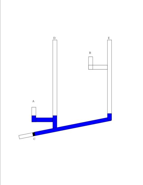
Clogged Fluid Passage Schematic Diagram - Tube Fill Levels A-E (Ford Bronco Ref)

Reference · 1987-1991 BroncoAll 110 schematics




Simple routing schematic with branching lines and points labeled A through E.
Part of 1987-1991 Ford Bronco Schematics
This document is a simple hand-drawn schematic (uploaded as 'Clog.jpg') consisting of a diagram with five labeled points, A, B, C, D, and E, and no explanatory text, part numbers, or specifications. The drawing depicts a system of interconnected tubes or passages: two tall vertical tubes (D and E), two short vertical stubs (A and B) joined to the system by horizontal segments, and a long diagonal passage running from the lower left (labeled C) up to the base of tube E. Blue shading indicates fluid filling the diagonal passage and the lower portions of tubes A, D, and E, while a small black band near point C appears to represent a clog or blockage in the line; the branch containing B and its connection to E is shown empty of fluid. The diagram appears intended as a conceptual illustration, likely explaining how a clog in a fluid passage affects fluid levels or flow in connected branches, rather than a vehicle-specific wiring or fuse chart. It was filed in a 1990 Ford Bronco gallery alongside other reference schematics, but the drawing itself contains no year, make, model, or system identification.
Is this accurate? Sign in to help verify it.
Frequently asked questions
- What does this diagram show?
- It shows a network of connected tubes labeled A through E, with blue shading indicating fluid filling some passages and a black band near point C that appears to represent a clog or blockage.
- Where is the clog located in the diagram?
- A small black band is drawn in the long diagonal tube near label C, at its lower-left end, indicating the blockage point.
- Which tubes contain fluid in the diagram?
- Blue shading fills the diagonal passage from C, the lower portions of vertical tubes D and E, and tube A with its horizontal connector; tube B and its connection to E are shown empty.
- Does the diagram include any part numbers, measurements, or vehicle information?
- No. The only text visible is the five labels A, B, C, D, and E, there are no part numbers, dimensions, or vehicle identifications.






No comments yet.