SuperMotors SuperMotors SUPERMOTORS Search: try “orange Bronco on 35s”
Home/ Registry/ Ford/ Bronco/ 1987-1991/ 1990 Ford Bronco/ Photo supermotors.net/registry/media/982294

Ford Bronco RABS Module Harness Connector Pin View - Pin #2 Location Diagram

14-pin module harness connector pin view diagram with pin 2 callout and ground
14-pin module harness connector pin view diagram with pin 2 callout and groundOriginal file
14-pin module harness connector pin view diagram with pin 2 callout and ground

Reference · 1987-1991 BroncoAll 175 wiring diagrams

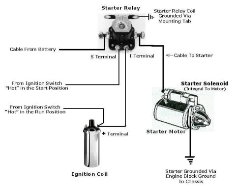
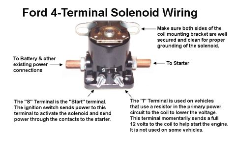
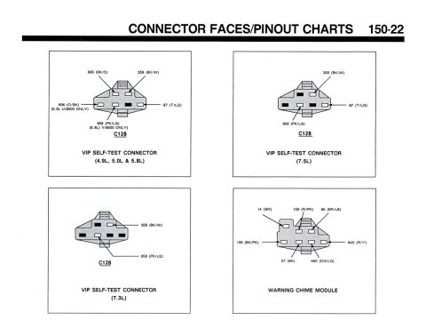
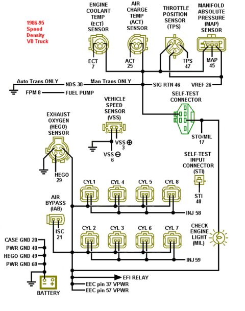
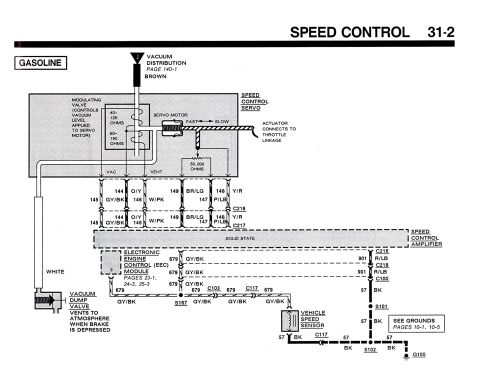
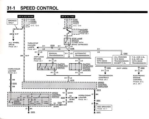
Ford Bronco RABS Module Harness Connector Pin View - Pin #2 Location Diagram Ford RABS Module Harness Connector Pin View Diagram - Pins 1 & 9 (1990 Bronco) 110V/220V Split-Phase Wiring Diagram - Black, White & Red Wire Voltages Ford 3G Alternator Wiring Diagram - Mega Fuse, Charge Lamp & Wire Colors 1973-1974 Ford Point-Type Ignition System Circuit Diagram - Coil & Distributor Ford 4-Terminal Starter Relay Wiring Diagram - S & I Terminals, Coil & Starter Ford 4-Terminal Starter Solenoid Wiring Diagram - S & I Terminal Functions KC Driving Lights & LED Light Bar Relay Wiring Diagram - Ford Bronco Aux Lights Connector faces page 150-22 with C128 VIP self-test connector pinouts and warning chime module 1986-95 Ford V8 Truck Speed Density EEC-IV Pinout Wiring Diagram 1990 Ford Bronco Speed Control Wiring Diagram 31-2 - Cruise Servo & Amplifier 1990 Ford Bronco Speed Control Wiring Diagram 31-1 - Cruise Control Circuit 175wiring diagrams1987-1991 Ford Bronco More reference Ford Bronco PCV System Airflow Diagram - Crankcase Ventilation Flow SchematicSchematic How to Find TDC for Distributor Installation - Ford Firing Order & Valve OverlapService procedure Ford Bronco 'America's Truck. Built Ford Tough.' print ad with red Bronco and feature sketchesBrochure Welder Input Data Plate - Serial JH229505, Stock 901782, 200/230/460V SpecsSpec plate Ford 5.0L V8 PCV Valve & Hose Routing Diagram - 9A474, 6B890, 6A664Exploded parts Ford 5.0L/5.8L Air Throttle Body Assembly Diagram - Canister Purge Ports & TPSManual page Tubing Adapter Blueprint 2.00" OD x 1.375" ID x 3" - 1.125"-12 TPI RH ThreadBlueprint '89 Ford vehicle emission control information label with EEC IV/EFI timing steps and vacuum hose routingVacuum routing 1990 Ford Bronco Fuse Panel Diagram: Fuse Positions, Amps & Circuits (11-2)Fuse chart Ford V8 Intake Manifold Bolt Tightening Sequence Diagram - Stud LocationsTorque spec

Pin-view diagram of a 14-pin module harness connector (two rows, pins 1-8 lower and 9-14 upper) with pin 2 highlighted and a ground symbol at left.

Part of 1987-1991 Ford Bronco Wiring Diagrams

AI caption · Photo 556 of 700

This document is a simple line drawing showing the pin-out view of a 14-pin module harness connector, uploaded as a reference for the RABS (Rear Anti-lock Brake System) module on a 1990 Ford Bronco. The diagram shows the connector face as viewed with two rows of pins: the top row contains pins 14, 13, 12, 11, 10, and 9 (with a blank rectangular keying block between pins 12 and 11), and the bottom row contains pins 8, 7, 6, 5, 4, 3, 2, and 1. An arrow specifically calls out Pin #2 in the bottom row, which is the focus of this page. A ground symbol is drawn to the left of the connector. The drawing is labeled 'Module Harness Connector: Pin View.' No wire colors, part numbers, year/model applicability, or additional text appear in the image. A reader can use this diagram to identify the physical location of Pin #2 (and the numbering of all 14 pins) when probing or testing the module harness connector, such as during RABS diagnostic testing.

Is this accurate? Sign in to help verify it.

Frequently asked questions

Where is Pin #2 on the RABS module harness connector?
Pin #2 is in the bottom row of the connector, second from the right end (between pins 3 and 1), as indicated by the arrow callout in the pin view diagram.
How many pins does the module harness connector have?
The diagram shows 14 numbered pins: pins 9 through 14 in the top row and pins 1 through 8 in the bottom row.
How are the pins arranged on the connector?
In the pin view, the top row reads 14, 13, 12, then a blank block, then 11, 10, 9; the bottom row reads 8, 7, 6, 5, 4, 3, 2, 1.
Is this diagram shown from the pin side or wire side of the connector?
The drawing is labeled 'Pin View,' indicating it shows the connector as viewed from the pin (face) side.


Comments

No comments yet.

More 1987-1991 Broncos