1978 Ford Bronco Custom Center Console Sketch - Gauges, Switches & Fan Lights

Reference · 1978-1979 BroncoAll 44 schematics
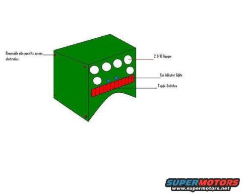
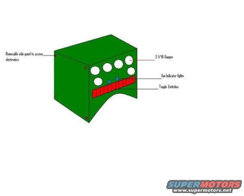
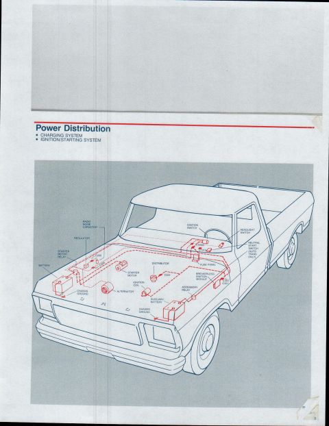
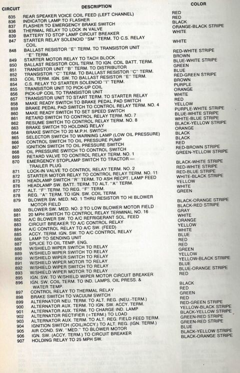



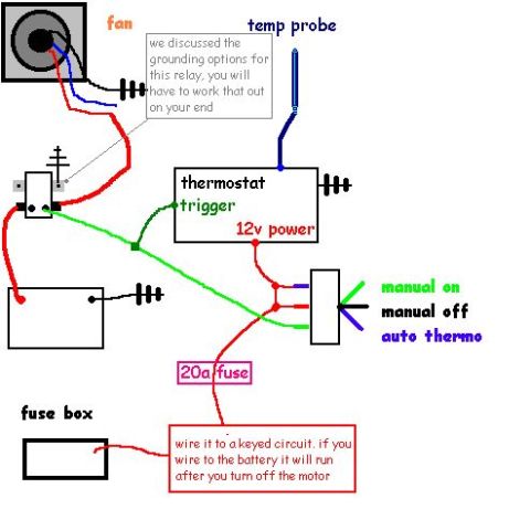
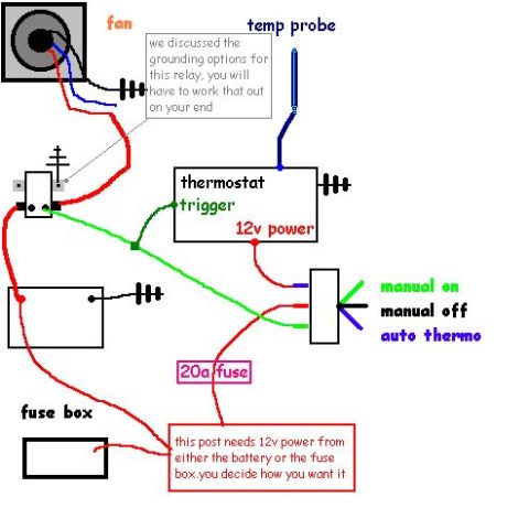




Technical layout drawing of a fabricated dash/electronics console with callouts for gauges, fan indicator lights, toggle switches, and a removable access panel.
Part of 1978-1979 Ford Bronco Schematics
This document is a simple computer-drawn concept schematic (labeled sketch) of a custom center console design, uploaded to the gallery of a 1978 Ford Bronco. It depicts a green box-shaped console in a 3D perspective view with four labeled callouts. Across the top face of the console are five circular openings identified as "2 1/16 Gauges" (2-1/16 inch diameter gauges). Below the gauge holes are two small blue dots labeled "Fan Indicator lights." Beneath those is a red horizontal strip divided into multiple segments labeled "Toggle Switches." On the left side of the console, a callout indicates a "Removable side panel to access electronics," with red dots at the panel corners apparently representing fasteners. The drawing contains no dimensions, part numbers, wiring information, fuse data, or year/model applicability text, it is purely a layout/design mockup showing the intended arrangement of gauges, indicator lights, and switches in a homemade or custom center console. A reader can learn the planned component layout: five 2-1/16" gauges on top, fan indicator lights below them, a row of toggle switches at the bottom, and side-panel access for servicing the electronics behind the console face.
Is this accurate? Sign in to help verify it.
Frequently asked questions
- What size gauges are shown in this center console design?
- The console design calls for 2 1/16 (2-1/16 inch) gauges, shown as five circular openings on the top face of the console.
- How is the electronics accessed in this console design?
- Through a removable side panel on the console, labeled 'Removable side panel to access electronics.'
- What controls and indicators are included in the console layout?
- The layout includes 2 1/16 gauges, fan indicator lights (shown as two small blue dots), and a row of toggle switches (shown as a segmented red strip).
- Does this document include wiring or fuse information?
- No. It is only a labeled layout sketch of the console; no wiring colors, fuse ratings, dimensions, or part numbers are shown.






No comments yet.