1978 Ford Bronco Ignition System Diagram - Coil, Distributor & Module Wiring

Reference · 1978-1979 BroncoAll 44 schematics
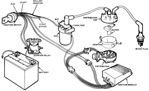
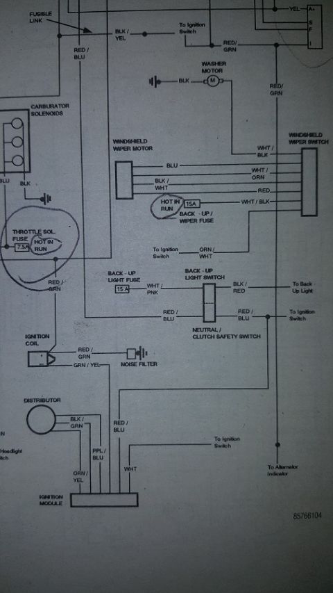
Schematic of the ignition system showing the ignition switch, ballast resistor, coil, distributor, ignition module and starter relay.
Part of 1978-1979 Ford Bronco Schematics
This document is a pictorial schematic of an automotive ignition system, uploaded to a 1978 Ford Bronco gallery under the filename 'Ignition Coil.gif'. It is a line-art illustration showing the major ignition system components and their wiring interconnections. Labeled components include the ignition switch (with RUN and START terminals identified), the ballast resistor, the start bypass wire, the ignition coil (with its BAT terminal and TACH TEST connector called out), the distributor cap, rotor, adapter, distributor body, a spark plug with plug wire and boot, the starter relay, the battery, and the ignition module. The drawing traces the wiring harness routing from the ignition switch through the ballast resistor to the coil, connections between the battery and starter relay, and the harness connectors joining the distributor and ignition module. The exploded view of the distributor cap, rotor, and adapter shows how those pieces stack onto the distributor. No part numbers, wire colors, torque values, model years, or engine applications are printed on the diagram itself. A reader can learn the overall layout and interconnection of a module-controlled (electronic) ignition system with a ballast resistor and start-bypass circuit, useful for identifying components and understanding wiring routing during diagnosis or repair.
Is this accurate? Sign in to help verify it.
Frequently asked questions
- What components are shown in this ignition system diagram?
- The diagram labels the ignition switch (RUN and START), ballast resistor, start bypass wire, coil (with BAT and TACH TEST terminals), distributor cap, rotor, adapter, distributor, spark plug, starter relay, battery, and ignition module.
- Where does the ballast resistor connect in this system?
- The ballast resistor is shown in the wiring coming from the ignition switch, in the circuit feeding the coil, with a separate start bypass wire around it.
- What terminals are identified on the ignition coil?
- The coil is shown with a BAT terminal and a TACH TEST connection.
- How do the distributor cap, rotor, and adapter fit together?
- The diagram shows an exploded view: the distributor cap on top, then the rotor, then the adapter, all stacking onto the distributor body.
- Is the ignition module connected to the distributor?
- Yes, the diagram shows wiring harness connectors linking the distributor to the ignition module.
No comments yet.