Ford 351M & 400 V8 Firing Order Diagram - Distributor Wiring & Timing Marks

Reference · 1978-1979 BroncoAll 44 schematics



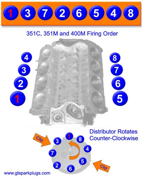
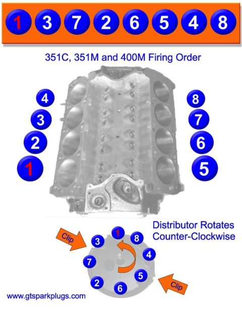



Firing order diagram showing spark plug wire routing on the distributor cap and timing pointer for 351M and 400 V8 engines.
Part of 1978-1979 Ford Bronco Schematics
This document is a spark plug wiring and firing order schematic for Ford 351M and 400 cubic-inch V8 engines. The diagram shows a top view of the engine with cylinder numbering: cylinders 8, 7, 6, 5 on one bank and 4, 3, 2, 1 on the other. A central distributor cap illustration shows the terminal positions (8, 4, 5, 6, 2, 7, 3, 1 arranged around the cap) with plug wires routed to each cylinder, and an arrow indicating the direction of rotor rotation. A note states that on 351M and 400 engines equipped with Frigidaire A/C only, the timing pointer is viewed from the left, while on all other applications it is viewed from the right. An inset detail of the crankshaft damper and timing pointer is labeled "FRONT" and shows the ignition timing scale graduations: BTDC, 30°, 20°, 10°, TC (top center), 10°, and ATDC. A reader can use this diagram to correctly route spark plug wires from the distributor cap to each cylinder and to locate and read the timing marks when setting ignition timing on these engines.
Is this accurate? Sign in to help verify it.
Frequently asked questions
- Which engines does this firing order diagram apply to?
- The diagram references Ford 351M and 400 engines, noting a special timing pointer viewing position for 351M & 400 engines with Frigidaire A/C.
- How are the cylinders numbered on the 351M/400 engine?
- One bank is numbered 8, 7, 6, 5 and the other bank is numbered 4, 3, 2, 1, as shown from the top view in the diagram.
- From which side is the timing pointer viewed?
- On 351M & 400 engines with Frigidaire A/C only, the timing pointer is viewed from the left; on all other applications it is viewed from the right.
- What timing marks are shown on the damper scale?
- The timing scale shows BTDC, 30°, 20°, 10°, TC (top center), 10°, and ATDC.
- Does the diagram show distributor rotor rotation direction?
- Yes, an arrow on the distributor cap illustration indicates the rotor's direction of rotation (counterclockwise as drawn).






No comments yet.