Home/
Registry/
Ford/
Taurus/
1992-1995/
1993 Ford Taurus/
Photo
supermotors.net/registry/media/593151
Ford Taurus SHO JBL CD Player Wiring Diagram 130-10 - Radio High Level Audio

Reference · 1992-1995 TaurusAll 37 wiring diagrams
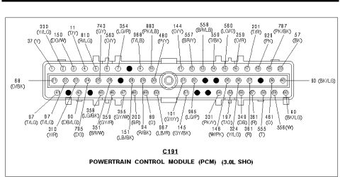
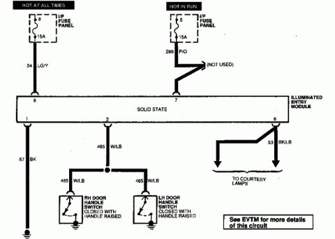
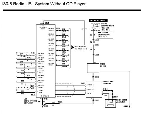
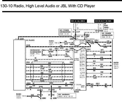
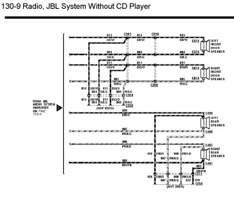

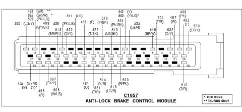
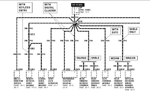
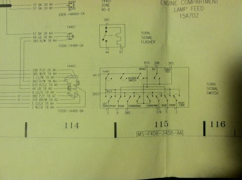

Wiring diagram for high-level audio or JBL with CD player showing CD player, radio and speaker circuit connections.
Part of 1992-1995 Ford Taurus Wiring Diagrams
This is page 130-10 of a Ford factory wiring diagram set, titled "Radio, High Level Audio or JBL With CD Player." It shows the electrical wiring between the CD player, the radio, and the vehicle's power and ground circuits for the high-level (JBL) audio system. Power comes from the instrument panel fuse panel: fuse 8 (15A, hot at all times) and fuse 11 (20A, hot in accessory or run), feeding circuits 54 (LG/Y) and 137 (Y/BK) through connector C257. The diagram details connectors C259, C262, C265, C287, C280, C281, and C257, splices S258 and S263, and grounds G203 and G103. Circuit numbers and wire colors are given, including 595 LB/R, 747 O/LB, 434 LB/BK, 484 O/BK, 19 LB/R (instrument illumination), speaker circuits 277 LB/BK, 859 Y, 278 P/W, 855 LB, 279 W/R, 858 BR, 280 LG, 857 W/O, logic mute circuit 689/68 DB, and grounds 694 R and 57 BK. The radio connector pin functions are labeled for all four speaker signal pairs (LF/RF/LR/RR, + and -), knob illumination feed, logic mute, and grounds. Cross-references point to power distribution (pages 13-10, 13-16), radio pages 130-5 and 130-7, instrument illumination pages 71-3/71-4, and grounds pages 10-9, 10-13.
Is this accurate? Sign in to help verify it.
Frequently asked questions
- What fuses power the JBL/high-level audio CD player system?
- Fuse 8 (15A, hot at all times) and fuse 11 (20A, hot in accessory or run) in the I/P fuse panel, feeding circuit 54 (LG/Y) and circuit 137 (Y/BK).
- What wire colors are used for the radio speaker circuits in this diagram?
- Speaker circuits at connector C281 include 277 LB/BK, 859 Y, 278 P/W, 855 LB, 279 W/R, 858 BR, 280 LG, and 857 W/O, corresponding to the LR, RR, RF, and LF speaker signal pairs.
- Where does the radio/CD player system ground?
- Ground circuits 694 (R) and 57 (BK) run through splices S258 and S263 and connector C257 to grounds G203 and G103. See grounds pages 10-9 and 10-13.
- Which circuit provides instrument illumination to the CD player?
- Circuit 434 LB/BK through connector C257 to 484 O/BK at C280, plus circuit 19 LB/R for the knob illumination feed.
- What circuit is used for the logic mute function?
- Circuit 689 DB from C280 through connector C257 to circuit 68 DB, connecting to the radio's logic mute pin 8.

No comments yet.