Home/
Registry/
Ford/
Taurus/
1996-1999/
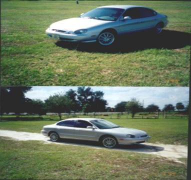
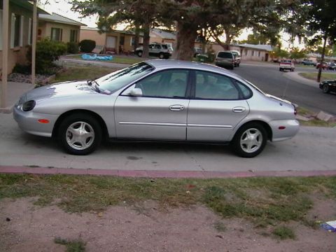
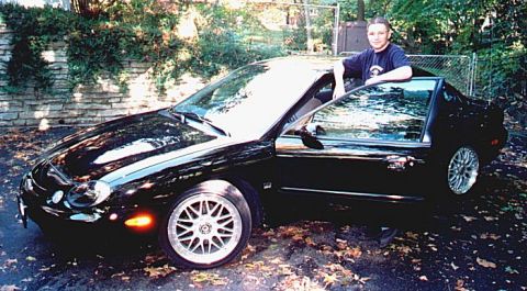
1997 Ford Taurus/
Photo
supermotors.net/registry/media/617692
Ford Transmission Range (TR) Sensor Location & Alignment Tool T92P-70010-AH

Reference · 1996-1999 TaurusAll 18 service procedures
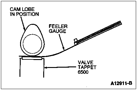
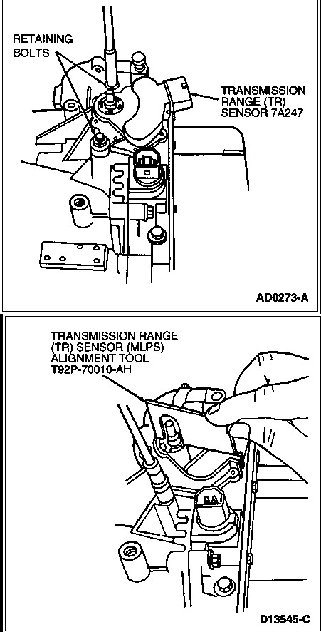
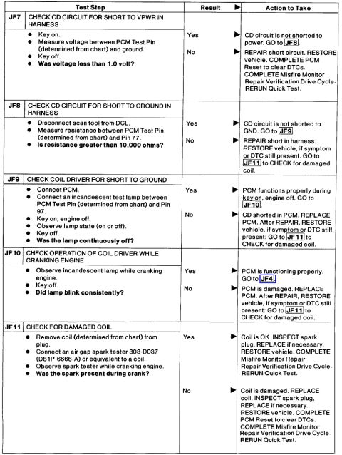
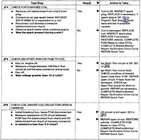
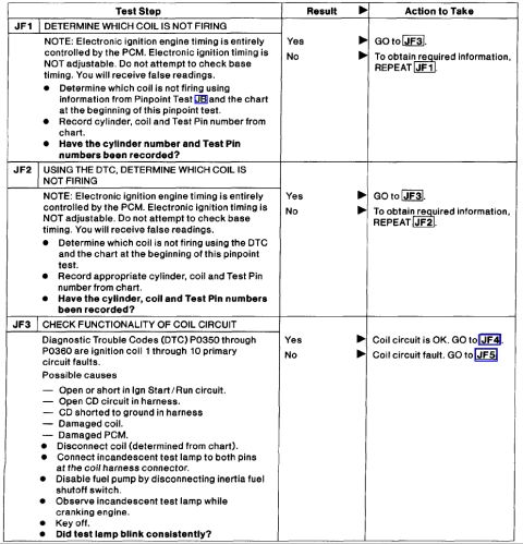
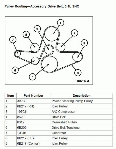
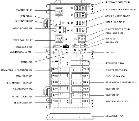
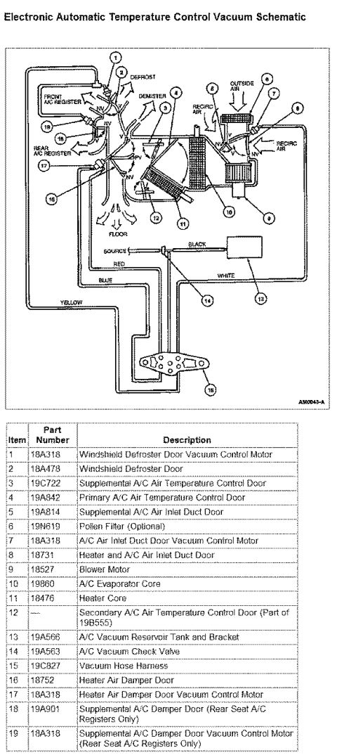

Service illustration showing transmission range (TR) sensor removal with retaining bolts and the MLPS alignment tool.
Part of 1996-1999 Ford Taurus Service Procedures
This document contains two service illustration diagrams related to the Transmission Range (TR) sensor on a Ford automatic transmission. The first illustration (figure ID AD0273-A) shows the location of the Transmission Range (TR) Sensor, identified by Ford base part number 7A247, mounted on the side of the transmission case at the manual shift shaft. Callouts identify the sensor itself and its two retaining bolts. The second illustration (figure ID D13545-C) shows the sensor alignment procedure: a technician's hand is depicted placing the Transmission Range (TR) Sensor (MLPS) Alignment Tool, Ford special service tool number T92P-70010-AH, over the sensor and shift shaft to correctly position the sensor before tightening the retaining bolts. No torque specifications, wire colors, or connector pin data are included in the scan, it is purely a component location and tool usage illustration. A reader can learn where the TR sensor is mounted, that it is secured by two retaining bolts, the base part number of the sensor (7A247), and the specific alignment tool required (T92P-70010-AH) to align the sensor during installation or adjustment. The document was uploaded as part of a 1997 Ford Taurus reference album but does not itself state a year, model, or engine application.
Is this accurate? Sign in to help verify it.
Frequently asked questions
- Where is the Transmission Range (TR) sensor located?
- The diagram (AD0273-A) shows the TR sensor (part 7A247) mounted on the side of the transmission at the manual shift shaft, secured by retaining bolts.
- What tool is used to align the Transmission Range sensor?
- The Transmission Range (TR) Sensor (MLPS) Alignment Tool, Ford tool number T92P-70010-AH, as shown in figure D13545-C.
- What is the Ford base part number for the TR sensor?
- The diagram labels the Transmission Range (TR) Sensor as part 7A247.
- How is the TR sensor held in place?
- The first illustration shows the sensor is secured by retaining bolts, which are identified by a callout.



No comments yet.