Ford Pinpoint Test JF4-JF6: Ignition Coil & Coil Driver Circuit Misfire Diagnosis

Coil-On-Plug pinpoint test (JF4-JF6): air-gap spark-test coil with 303-D037 (D81P-6666-A), confirm IGN Start/Run voltage >10.5V and coil-driver (CD) circuit resistance <5.0 ohms.
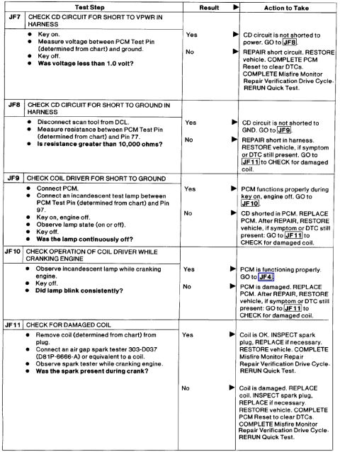
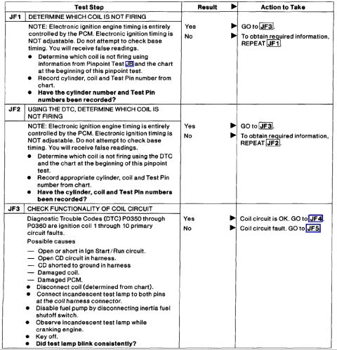
This document is one page of a Ford pinpoint diagnostic test procedure covering steps JF4 through JF6 for diagnosing ignition coil and coil driver circuit problems related to engine misfire. Step JF4 (Check for Damaged Coil) instructs the technician to remove the suspect coil, connect an air gap spark tester (tool 303-D037 / D81P-6666-A), and observe for spark while cranking; presence of spark points to Pinpoint Test Z1, while absence indicates a damaged coil requiring replacement. Step JF5 (Check IGN Start/Run Voltage to Coil) tests for greater than 10.5 volts at the coil harness connector with key on/engine off; failure directs checking related fuses/fuse links and repairing open or shorted circuits. Step JF6 (Check Coil Driver CD Circuit for Open in Harness) uses a breakout box with the PCM disconnected to verify the CD circuit resistance is less than 5.0 ohms; a pass leads to step JF7, a fail requires open-circuit repair. Each failure path ends with restoring the vehicle, completing a PCM reset to clear DTCs, completing the Misfire Monitor Repair Verification Drive Cycle, and rerunning the Quick Test. This page helps diagnose no-spark/misfire conditions on coil-on-plug or distributorless ignition systems.
Is this accurate? Sign in to help verify it.
Frequently asked questions
- What spark tester is specified for checking a damaged coil in step JF4?
- An air gap spark tester 303-D037 (D81P-6666-A) or equivalent, connected to the coil while observing spark during engine cranking.
- What voltage should the IGN Start/Run circuit show at the coil harness connector in step JF5?
- With key on, engine off, the voltage between the IGN Start/Run circuit at the coil harness connector and ground should be greater than 10.5 volts.
- What is the resistance specification for the coil driver (CD) circuit in step JF6?
- Measured with a breakout box installed and the PCM disconnected, the CD circuit resistance between the PCM test pin and CD at the harness connector should be less than 5.0 ohms.
- What do I do after replacing a damaged coil per JF4?
- Inspect the spark plug and replace if necessary, restore the vehicle, complete a PCM Reset to clear DTCs, complete the Misfire Monitor Repair Verification Drive Cycle, and rerun the Quick Test.
- What if the IGN Start/Run voltage test fails in JF5?
- Check the condition of related fuses/fuse links. If they are OK, repair the open circuit; if a fuse/fuse link is damaged, check the Ign Start/Run circuit for a short to ground and repair as necessary, then complete the Misfire Monitor Repair Verification Drive Cycle and rerun the Quick Test.
Comments
More from this build


No comments yet.