Home/
Registry/
Ford/
Taurus/
1996-1999/
1997 Ford Taurus/
Photo
supermotors.net/registry/media/683984
Ford Valve Clearance Check Diagram - Feeler Gauge Between Cam Lobe & Tappet 6500

Reference · 1996-1999 TaurusAll 18 service procedures
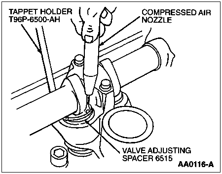
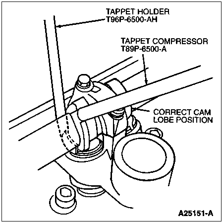
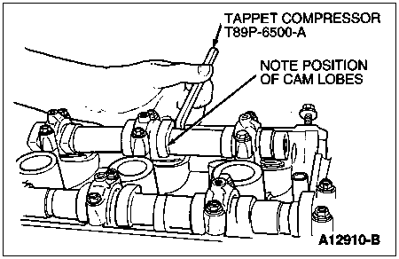
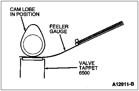

Service illustration showing a feeler gauge checking clearance at the valve tappet with the cam lobe in position.
Part of 1996-1999 Ford Taurus Service Procedures
This document is a single-page service illustration showing how to check valve clearance on an overhead-cam engine. The line drawing depicts a cam lobe positioned above a valve tappet, with a feeler gauge inserted between the base circle of the cam lobe and the top of the tappet (shim surface). Three callouts label the components: 'CAM LOBE IN POSITION' pointing to the camshaft lobe, 'FEELER GAUGE' pointing to the gauge blade being slid into the clearance gap, and 'VALVE TAPPET 6500' identifying the tappet (6500 is the Ford base part number group for valve tappets/lifters). The figure carries the Ford illustration reference number A12911-B in the lower right corner. The image was uploaded as part of a set of valve-train service illustrations (shim removal with compressed air, tappet compressor placement, tappet holder placement), suggesting it belongs to a valve clearance adjustment procedure for a bucket-and-shim style valvetrain. A reader learns the correct measurement setup: rotate the cam so the lobe is properly positioned (base circle facing the tappet), then measure the gap with a feeler gauge between the cam lobe and the tappet. No numeric clearance specifications, torque values, or year/model applicability are stated on the page itself.
Is this accurate? Sign in to help verify it.
Frequently asked questions
- How is valve clearance measured in this diagram?
- A feeler gauge is inserted between the cam lobe (positioned over the tappet) and the top of the valve tappet to measure the clearance.
- What components are labeled in the illustration?
- Three items are labeled: the cam lobe in position, the feeler gauge, and the valve tappet (base part number 6500).
- What is the Ford illustration reference number for this figure?
- The figure is identified as A12911-B.
- Does the document give a specific valve clearance specification?
- No. The illustration shows the measurement setup only; no numeric clearance values appear on this page.


No comments yet.