Home/
Registry/
Ford/
Taurus/
1996-1999/
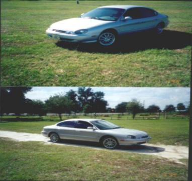
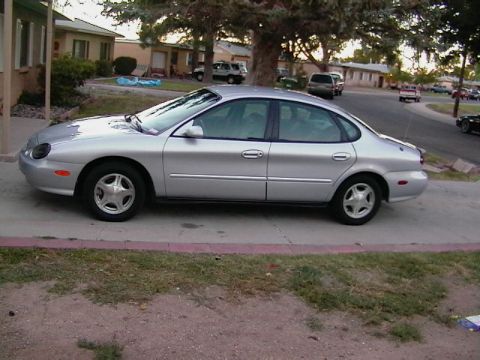
1997 Ford Taurus/
Photo
supermotors.net/registry/media/683991
Ford Valve Shim Removal with Compressed Air - Tappet Holder T96P-6500-AH Diagram

Reference · 1996-1999 TaurusAll 18 service procedures
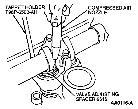
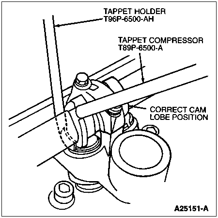
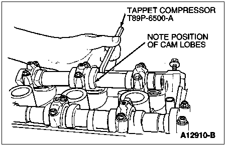
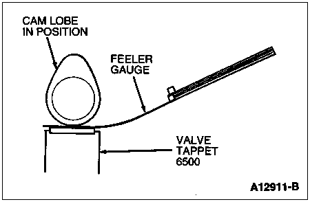
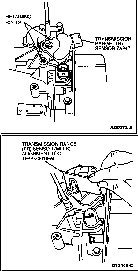
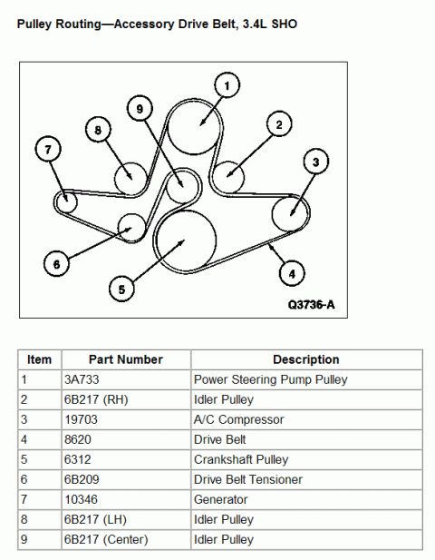
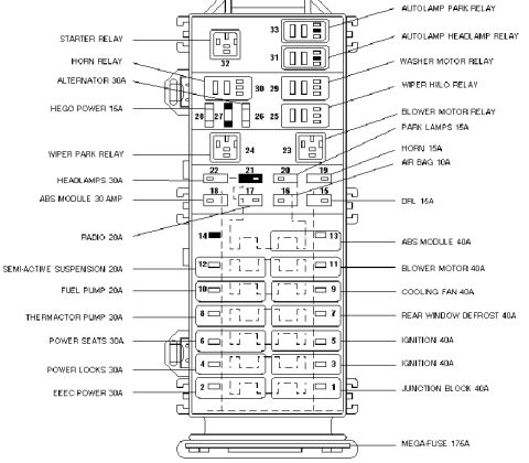
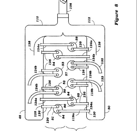
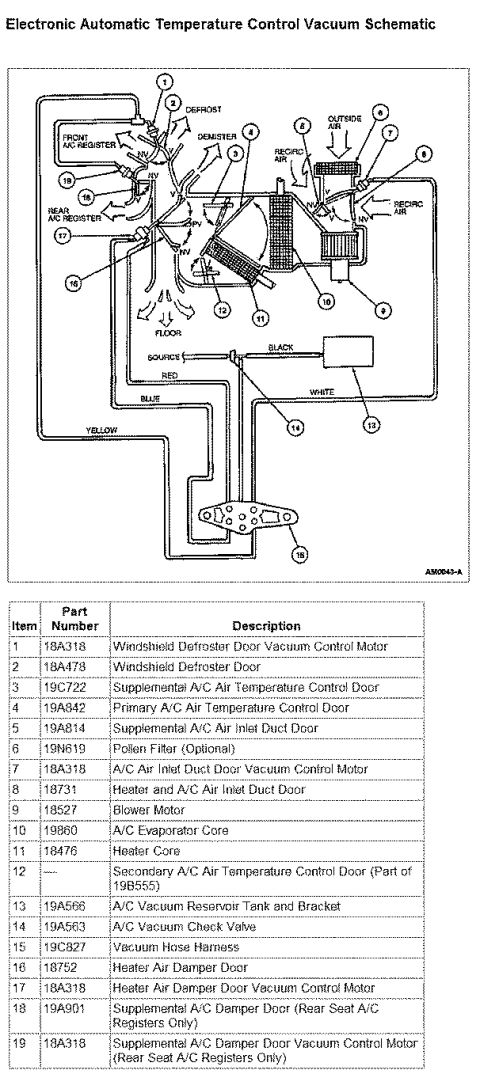

Service illustration showing valve adjusting spacer removal using tappet holder tool and a compressed air nozzle.
Part of 1996-1999 Ford Taurus Service Procedures
This is a single-page illustration from a Ford service procedure showing how to remove a valve adjusting spacer (shim) using compressed air. The line drawing depicts a cylinder head with an overhead camshaft, on which the special service tool Tappet Holder T96P-6500-AH is installed to hold the tappet (lifter) down while the camshaft remains in place. A hand-held compressed air nozzle is shown directed into the tappet bucket to blow the valve adjusting spacer (Ford base part number 6515) free so it can be removed and replaced with a different thickness shim to set valve clearance. The figure is labeled with three callouts, the tappet holder tool number, the compressed air nozzle, and the valve adjusting spacer, plus the figure reference number AA0116-A. The image is one page of a multi-page valve clearance adjustment procedure; companion pages in the same set cover checking valve clearance and placing the tappet compressor and tappet holder tools. A reader learns which special tool (T96P-6500-AH) is required, that compressed air is used to dislodge the shim, and the part designation (6515) of the adjusting spacer.
Is this accurate? Sign in to help verify it.
Frequently asked questions
- What special tool is used to hold the tappet during valve shim removal?
- The Tappet Holder, Ford tool number T96P-6500-AH, is shown installed to hold the tappet while the shim is removed.
- How is the valve adjusting spacer (shim) removed?
- A compressed air nozzle is directed at the tappet to blow the valve adjusting spacer free while the tappet holder keeps the tappet depressed.
- What is the part number of the valve adjusting spacer?
- The valve adjusting spacer is identified by base part number 6515.
- What is the figure reference number of this illustration?
- The illustration is labeled AA0116-A.




No comments yet.