Home/
Registry/
Ford/
Taurus/
1996-1999/
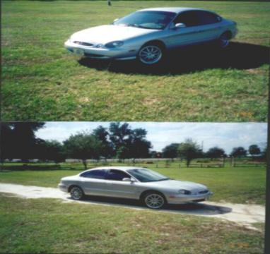
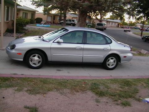
1997 Ford Taurus/
Photo
supermotors.net/registry/media/683985
Ford Tappet Compressor T89P-6500-A Placement Diagram - DOHC Valve Shim Service

Reference · 1996-1999 TaurusAll 18 service procedures
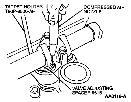
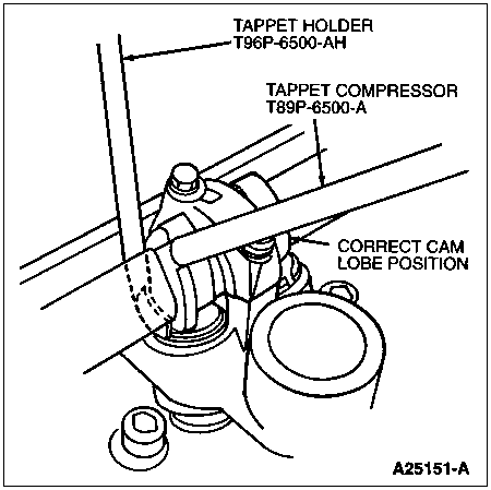
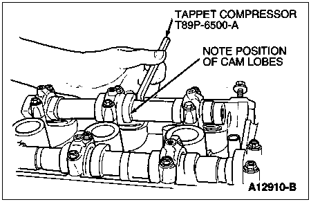
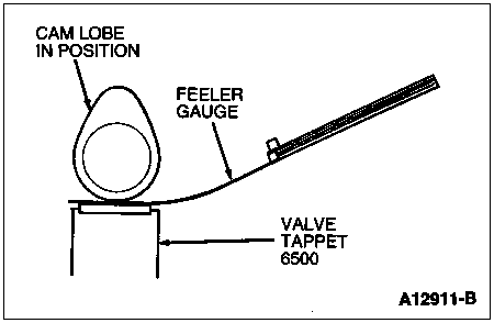

Service illustration showing use of tappet compressor tool T89P-6500-A while noting camshaft lobe position.
Part of 1996-1999 Ford Taurus Service Procedures
This is a single-page service illustration showing the placement of a valve tappet compressor tool during a valve adjustment procedure on a dual overhead cam (DOHC) engine. The line drawing depicts a technician's hand inserting the Tappet Compressor, Ford special service tool number T89P-6500-A, between the camshafts of the cylinder head to depress a valve tappet (lifter bucket). A callout instructs the technician to "NOTE POSITION OF CAM LOBES," indicating that the camshaft lobe orientation must be observed before compressing the tappet, typically so the lobe is not pressing on the tappet being serviced. The figure reference number A12910-B appears in the lower right corner. This illustration is part of a multi-page valve clearance adjustment set (companion pages include valve clearance check, shim removal with compressed air, and tappet holder placement), and this page specifically teaches where and how the tappet compressor tool is positioned on the cam carrier so the valve adjusting shims can be removed and replaced. No torque values, part numbers other than the tool number, or year/model applicability statements appear on this page.
Is this accurate? Sign in to help verify it.
Frequently asked questions
- What special tool is used to compress the tappets in this procedure?
- The Tappet Compressor, Ford tool number T89P-6500-A.
- What must be observed before compressing the tappet?
- The diagram instructs to note the position of the cam lobes before placing the tappet compressor.
- Where is the tappet compressor tool placed?
- The illustration shows the tool inserted between the camshafts on the cylinder head, pressed down by hand onto the tappet.
- What is the figure reference number of this illustration?
- A12910-B.



No comments yet.