Home/
Registry/
Ford/
Taurus/
1996-1999/
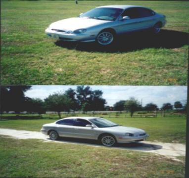
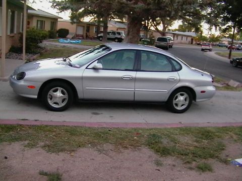
1997 Ford Taurus/
Photo
supermotors.net/registry/media/683986
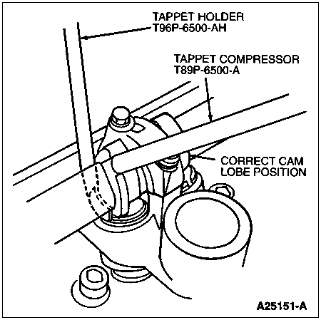
Ford Tappet Holder T96P-6500-AH & Compressor T89P-6500-A Placement Diagram
Reference · 1996-1999 TaurusAll 18 service procedures
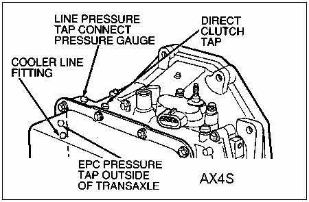
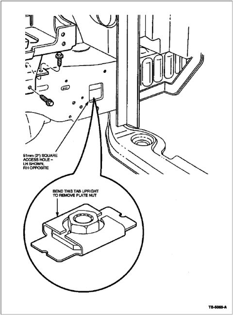
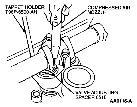
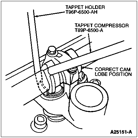
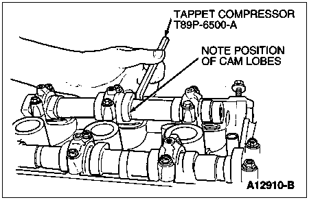
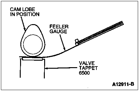
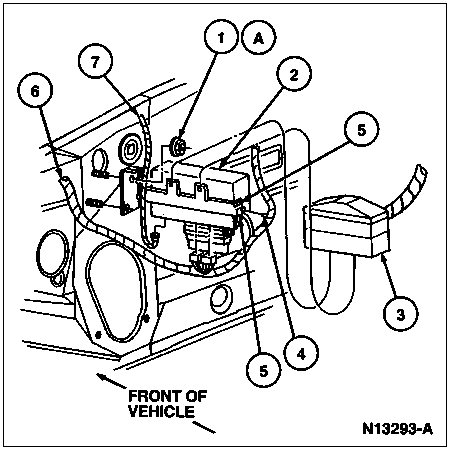
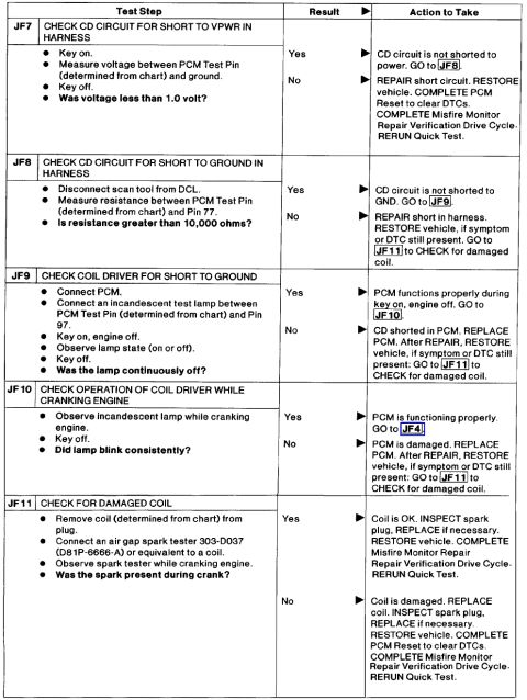
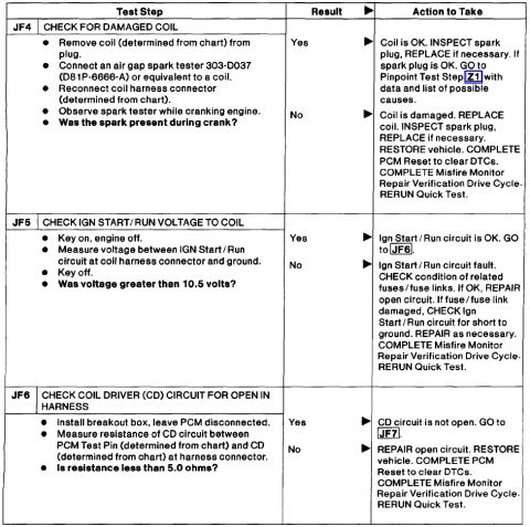
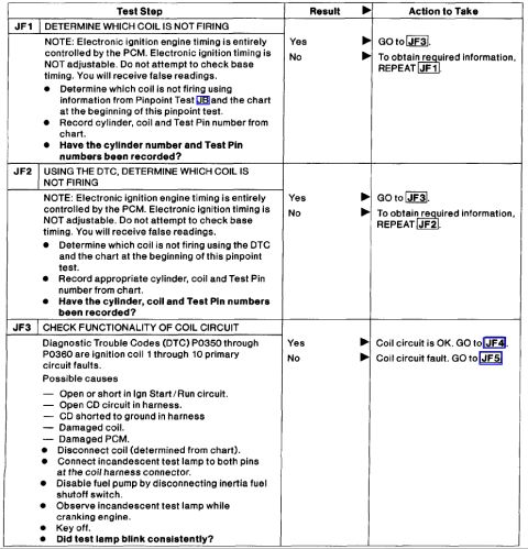

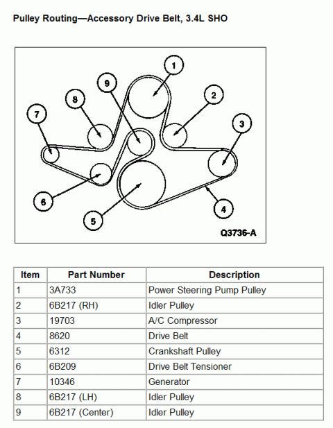
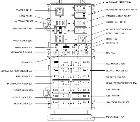
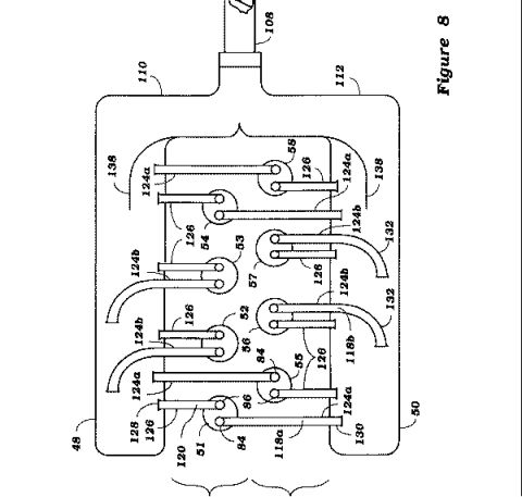
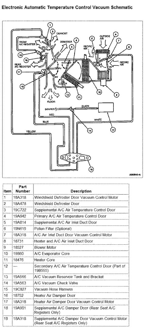

Service illustration showing tappet holder and tappet compressor tools positioned for correct cam lobe orientation.
Part of 1996-1999 Ford Taurus Service Procedures
This document is a single illustration from a service procedure showing the placement of special valvetrain service tools on an overhead-cam cylinder head. Two Ford special service tools are identified by callouts: the Tappet Holder, tool number T96P-6500-AH, and the Tappet Compressor, tool number T89P-6500-A. A third callout, labeled 'CORRECT CAM LOBE POSITION,' points to the camshaft lobe, indicating that the cam lobe must be oriented as shown (base circle facing the tappet/follower) before the tools are installed. The drawing shows the tappet compressor lever bearing on the tappet while the holder is inserted to retain the tappet in the depressed position, as would be needed for valve lash adjustment shim removal or replacement without removing the camshaft. The figure reference number A25151-A appears in the lower right corner. The image is part of an album that also includes pages for valve clearance checking, shim removal with compressed air, and tappet compressor placement, suggesting it belongs to a valve clearance (lash) adjustment procedure. No year, model, engine, torque values, or specifications are stated on this page itself; only the two special tool part numbers and the cam lobe positioning note are provided.
Is this accurate? Sign in to help verify it.
Frequently asked questions
- What is the part number for the Ford tappet holder tool?
- The tappet holder shown in the diagram is tool number T96P-6500-AH.
- What tool number is the tappet compressor?
- The tappet compressor is tool number T89P-6500-A.
- What must be checked before compressing the tappet with these tools?
- The diagram calls out the 'correct cam lobe position,' indicating the cam lobe must be positioned as shown before the tappet compressor and tappet holder are installed.
- How are the tappet compressor and tappet holder positioned?
- Per the illustration, the tappet compressor (T89P-6500-A) levers against the tappet while the tappet holder (T96P-6500-AH) is inserted from above to hold the tappet down, with the cam lobe in the correct position.




No comments yet.