Home/
Registry/
Ford/
Bronco/
1992-1996/
1996 Ford Bronco/
Photo
supermotors.net/registry/media/622618
1996 Ford Bronco Dana 44 Front Axle Exploded Parts Diagram (E9764-B)

Reference · 1992-1996 BroncoAll 169 exploded parts diagrams
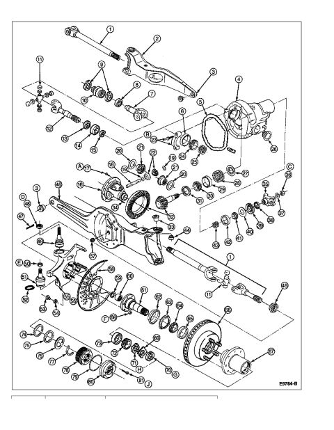

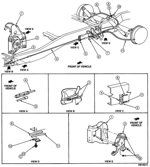
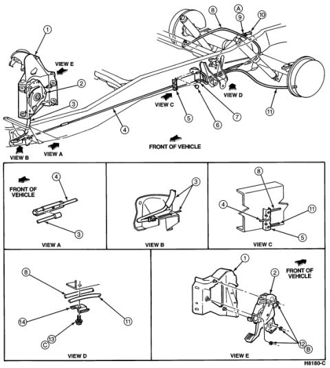
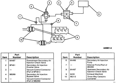
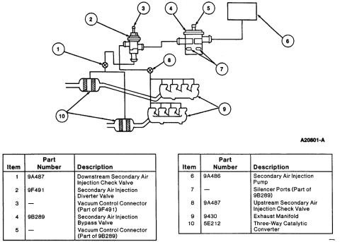
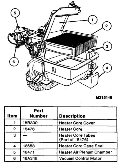
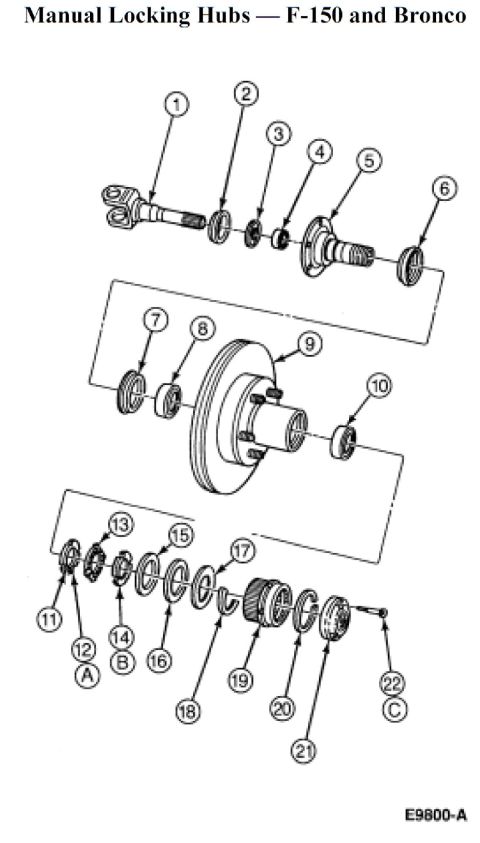

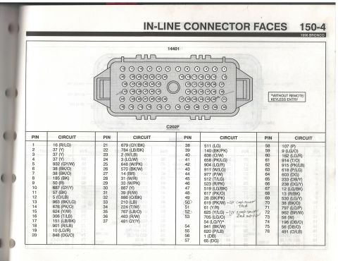
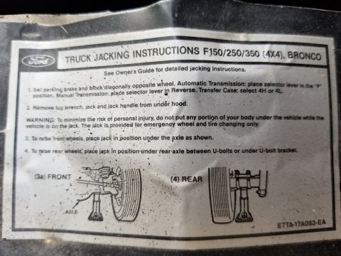







Exploded parts breakdown of a front drive axle and differential showing numbered components and brake rotor.
Part of 1992-1996 Ford Bronco Exploded Parts Diagrams
This document is a single-page exploded parts diagram of a front drive axle assembly, uploaded to a 1996 Ford Bronco gallery under the filename '96 Dana 44.jpg'. The illustration shows the complete disassembled front axle: axle shafts with U-joints and yokes (callouts 1, 11, 12), the differential carrier housing and cover/gasket area (4, 5), differential case, ring gear and pinion set, side gears, spider gears, bearings, shims and seals (16-34), the pinion yoke and nut (35-37), radius/support arms (2, 46), ball joints and steering knuckle components (48-54), spindle, brake dust shield, rotor and hub (55-67), and the locking hub / bearing / snap-ring stack (68-81). Callouts are numbered 1 through 81, with additional lettered references A through J marking sub-assembly groups. The only text on the page besides callout numbers is the Ford-style illustration code E9764-B in the lower right corner. A parts legend/table appears to have been cut off at the bottom of the scan, so part names and part numbers for each callout number are not available in this image. The diagram is useful for identifying assembly order and component relationships when rebuilding the front axle, hubs, and wheel bearings.
Is this accurate? Sign in to help verify it.
Frequently asked questions
- What does this diagram show?
- An exploded view of a front drive axle assembly, including axle shafts with U-joints, the differential carrier and internal gears/bearings, radius arms, ball joints, knuckle, spindle, brake rotor, hub, and locking hub components, with callouts numbered 1-81 and letters A-J.
- Does this diagram include a parts list with names or part numbers?
- No. Only the numbered/lettered callouts and the illustration code E9764-B are visible; the legend table at the bottom is cut off in this scan.
- How many numbered parts are identified in the exploded view?
- Callouts run from 1 to 81, plus lettered references A through J. Some numbers (such as 1, 3, 11, 19, 20, 21) appear more than once for duplicate parts.
- What is the figure reference code on this illustration?
- E9764-B, printed in the lower right corner of the diagram.






No comments yet.