Electric Fan Motor Wiring Diagram - 30A Relay & Temp Switch (1995 Ford Bronco)
Reference · 1992-1996 BroncoAll 411 wiring diagrams
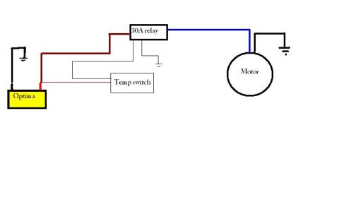










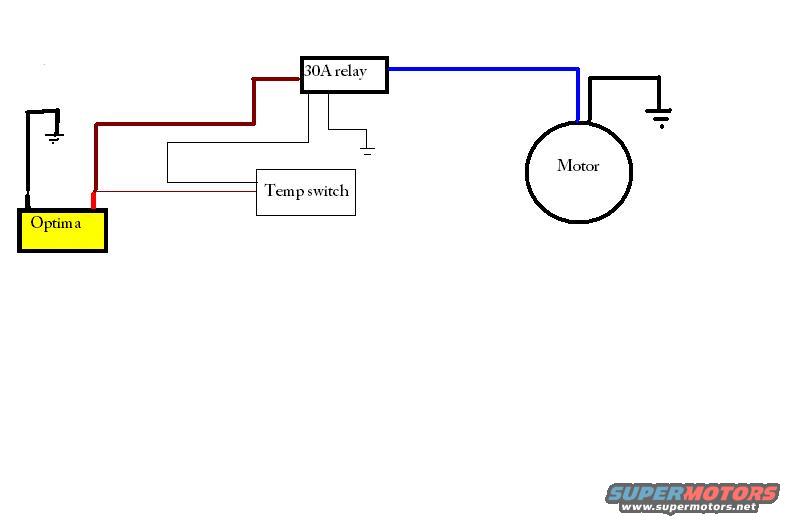
Wiring diagram showing color-coded connections between an Optima battery, 30A relay, temperature switch and an electric motor.
Part of 1992-1996 Ford Bronco Wiring Diagrams
This document is a simple, hand-drawn (computer-sketched) wiring diagram showing how to wire an electric motor, most likely an electric cooling fan, through a 30-amp relay controlled by a temperature switch, uploaded to the gallery of a 1995 Ford Bronco. The diagram contains four labeled components: an "Optima" battery (drawn as a yellow box), a "30A relay," a "Temp switch," and a "Motor." A heavy dark-red power wire runs from the battery to the relay, and a blue wire carries switched power from the relay to the motor. The motor and the relay each have their own chassis ground connections (shown with standard ground symbols), and the battery is also grounded. The temperature switch is wired into the relay's control circuit, with a thin trigger wire running back toward the battery side, so the switch energizes the relay coil and the relay handles the high-current load to the motor. A reader can learn the basic relay-triggered fan/motor circuit layout: battery feeds the relay, temp switch triggers the relay, relay powers the motor, and both relay and motor are grounded. No fuse values (other than the relay's 30A rating), wire gauges, pin numbers, or part numbers are given.
Is this accurate? Sign in to help verify it.
Frequently asked questions
- What amperage relay is used in this wiring diagram?
- The diagram specifies a 30A relay between the Optima battery and the motor.
- What triggers the relay in this diagram?
- A temp switch is wired into the relay's control circuit, so the relay is triggered by the temperature switch.
- What battery is shown powering the circuit?
- An Optima battery, drawn as a yellow box, supplies power via a red wire to the 30A relay.
- How is the motor grounded in this diagram?
- The motor has its own black wire running to a chassis ground symbol; the relay and battery also show separate ground connections.
- What wire colors are shown in the diagram?
- A dark red wire runs from the battery to the relay, a blue wire runs from the relay to the motor, and black wires are used for the grounds and switch/control connections.






No comments yet.