Home/
Registry/
Ford/
Bronco/
1992-1996/
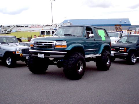
“The Green Machine”/
Photo
supermotors.net/registry/media/710105
90Beater Rock Sliders Blueprint - DIY Ford Bronco Slider Dimensions & Materials

Dimensioned fabrication drawing for rock sliders showing tubing and flat-stock measurements, a materials list and step-by-step cut and weld notes.
This document is a homemade blueprint titled "90Beater Rock Sliders," showing how to fabricate a set of DIY rock sliders (side frame protection) for a truck, credited to Topher's World (www.tophersworld.com). A dimensioned diagram identifies each labeled component: the main tube (A) is cut to 67 inches with 45-degree ends ("67 inches with points"), angled gussets (B) measure 3 inches with 45-degree cuts (x8 pieces), a lower tube (C) is measured after fitting A and B, end caps (D) are welded on after assembly, mounting plates (E) are 3 x 3 inches (except the rear driver's side at 3 x 2.5 inches to clear E-brake cables/brackets), vertical legs (F and G) measured 16 inches in the rear and 16.5 inches in the front, and a cross member (H) is measured and cut after G. Two 21-inch spacing dimensions locate the gussets along the slider. The material list calls for 40 feet of 1.5-inch square .120-wall tubing, 1.5 x 8 x .25-inch flat stock (x2), 3 x 3 x .25-inch flat stock (x3), plus sixteen each of 3/8 x 1.25-inch bolts, 3/8-inch nuts, washers, and lock washers. Step notes advise marking bolt holes after all welding/grinding and clearing items from the frame before drilling.
Is this accurate? Sign in to help verify it.
Frequently asked questions
- How long is the main tube (A) for the 90Beater rock sliders?
- Part A is cut to 67 inches with 45-degree cuts, dimensioned as "67 inches with points" (tips are cut off later in step D).
- What materials are needed to build these rock sliders?
- 40 feet of 1.5" square .120 wall tubing, 1.5" x 8" x .25" flat stock (x2), 3" x 3" x .25" flat stock (x3), plus 3/8" x 1.25" bolts (x16), 3/8" nuts (x16), 3/8" washers (x16), and 3/8" lock washers (x16).
- How tall are the vertical legs (F and G)?
- The builder measured 16" for the rear leg (F) and 16.5" for the front leg (G); the plan says to set the sliders in place and measure, and to measure more than once before cutting.
- Why is one mounting plate smaller than the others?
- The plates (E) are 3" x 3" except the rear driver's side, which is 3" x 2.5" due to E-brake cables/brackets.
- When should the mounting holes be marked and drilled?
- Per step H, mark the holes after all welding and grinding is done, and make sure to move anything from the frame before drilling.
Comments
More from this build




No comments yet.