Home/
Registry/
Ford/
Bronco/
1987-1991/
1991 Ford Bronco/
Photo
supermotors.net/registry/media/766489
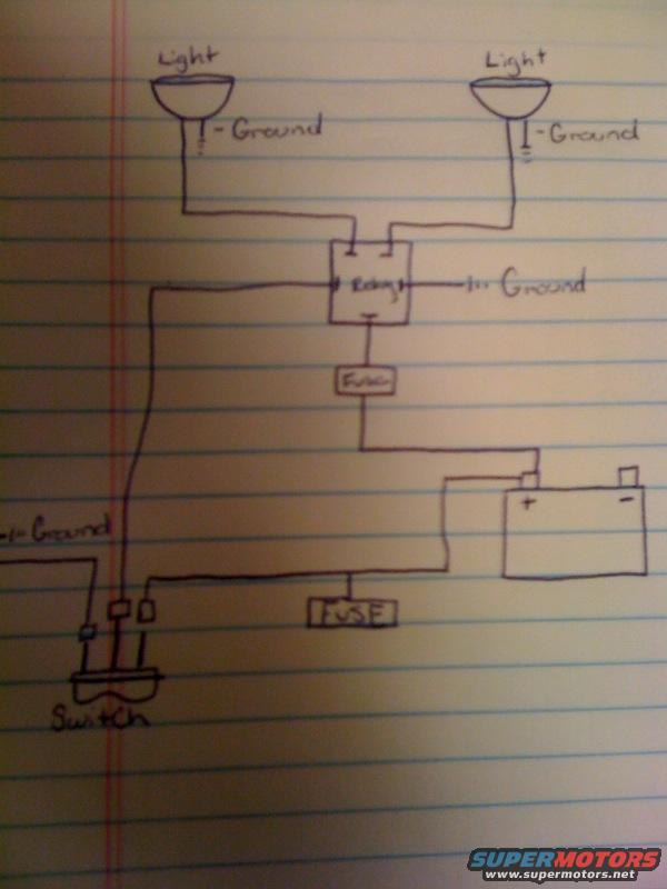
Hand-Drawn Auxiliary Light Relay Wiring Diagram - 1991 Ford Bronco Off-Road Lights
Reference · 1987-1991 BroncoAll 175 wiring diagrams
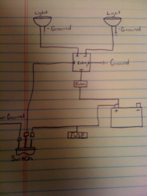
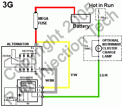
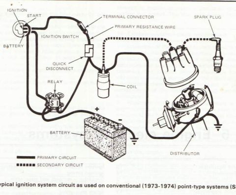
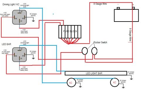
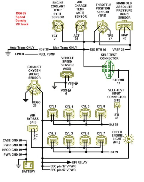
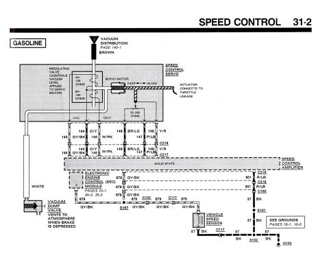
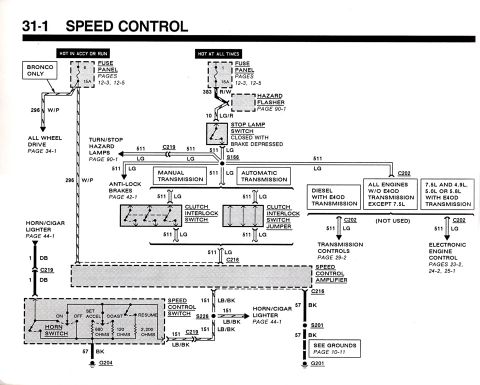
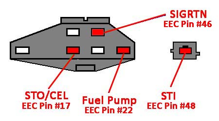





Hand-drawn wiring diagram showing two grounded lights wired through a relay and fuse to a battery and switch.
Part of 1987-1991 Ford Bronco Wiring Diagrams
This document is a hand-drawn wiring diagram, sketched in ink on lined notebook paper, showing how to wire a pair of auxiliary lights (such as off-road, fog, or driving lights) using a relay, two fuses, a toggle switch, and the vehicle battery. Two lights at the top are each individually grounded and share a common feed wire from one terminal of a centrally drawn relay. The relay itself has a ground connection. Power for the lights comes from the battery positive terminal through an inline fuse to the relay. A second fused wire runs from the positive/battery circuit to a dash-mounted switch, which controls the relay's coil; the switch circuit also shows a ground connection. A reader can learn the basic layout of a relay-controlled auxiliary lighting circuit: fused battery power to the relay's load side, fused switched power for the relay trigger, and separate grounds for the lights, relay, and switch circuit. The diagram contains no amperage ratings, wire colors, gauge sizes, part numbers, relay pin numbers, or vehicle-specific information, it is a generic schematic uploaded to a 1991 Ford Bronco gallery, and nothing in the drawing contradicts that application.
Is this accurate? Sign in to help verify it.
Frequently asked questions
- How are the auxiliary lights wired to the relay in this diagram?
- Both lights share a single feed wire from one relay terminal, and each light has its own separate ground connection.
- How many fuses does this light wiring diagram use?
- Two: one fuse inline between the battery positive terminal and the relay, and a second fuse on the wire feeding the switch circuit.
- Where does the relay get its power in this diagram?
- Directly from the battery positive (+) terminal through an inline fuse.
- Does the relay need a ground in this setup?
- Yes, the diagram shows a ground connection on the relay in addition to grounds at each light and at the switch circuit.
- Does the diagram specify fuse amperage or wire gauge?
- No. The fuses are labeled only as 'Fuse'/'FUSE' with no amp ratings, and no wire gauges or colors are given.






No comments yet.