Home/
Registry/
Ford/
Bronco/
1980-1986/
1982 Ford Bronco/
Photo
supermotors.net/registry/media/818132
Ford Bronco Kill Switch Wiring Diagram - Hella Battery Switch, Starter Circuit
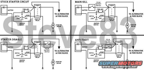
Wiring diagrams showing four starter circuit configurations with battery, ignition switch, starter relay and kill switches.
This document is a four-panel wiring diagram set (watermarked "Steve83") showing how to wire a Hella battery kill switch into a vehicle's starter circuit. The first panel, "STOCK STARTER CIRCUIT," shows the factory arrangement: battery to starter relay (with a fuse link feeding the ignition switch), starter relay to starter motor, and a lead labeled "TO ALTERNATOR & FUSE BLOCK." The ignition switch is drawn with its five positions: ACCY, LOCK, OFF, RUN, and START. The remaining three panels show alternative kill-switch installations: "MAIN KILL" places the Hella battery switch directly between the battery and the starter relay/fuse link, cutting all power; "STARTER DISABLE" places the switch between the starter relay output stud and the alternator/fuse block feed while the relay still powers the starter motor; and "ANTI-THEFT" places the switch in the small ignition-switch feed line downstream of the fuse link, so the ignition circuit (and thus starting) is disabled. All grounds are shown at the battery, ignition switch, and starter motor. A reader can use this page to choose and wire one of three kill-switch strategies using a Hella battery switch on a Ford-style starter circuit with an external starter relay.
Is this accurate? Sign in to help verify it.
Frequently asked questions
- What kill switch installation options does this diagram show?
- Three options plus the stock circuit: MAIN KILL, STARTER DISABLE, and ANTI-THEFT, each using a Hella battery switch wired into a different point of the starter circuit.
- Where does the Hella battery switch go for a main kill setup?
- In the MAIN KILL diagram, the Hella battery switch is placed between the battery positive and the starter relay/fuse link, cutting power to the entire circuit.
- How is the anti-theft configuration wired?
- In the ANTI-THEFT diagram, the Hella battery switch is placed in the fuse-link feed to the ignition switch side of the starter relay, so the ignition/start circuit is interrupted.
- What ignition switch positions are shown in the diagrams?
- ACCY, LOCK, OFF, RUN, and START.
- What components make up the stock starter circuit shown?
- Battery, fuse link, ignition switch, starter relay, starter motor, and a feed labeled 'TO ALTERNATOR & FUSE BLOCK.'
Comments
More from this build






No comments yet.