Ford Duraspark Ignition Module Wiring Diagram - 1982 Bronco Wire Colors
Reference · 1980-1986 BroncoAll 92 wiring diagrams
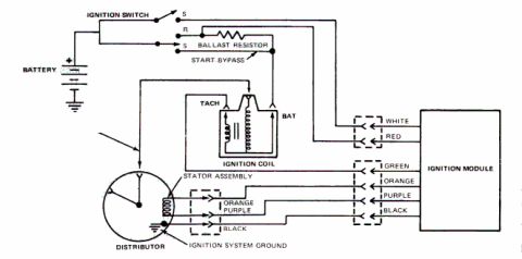







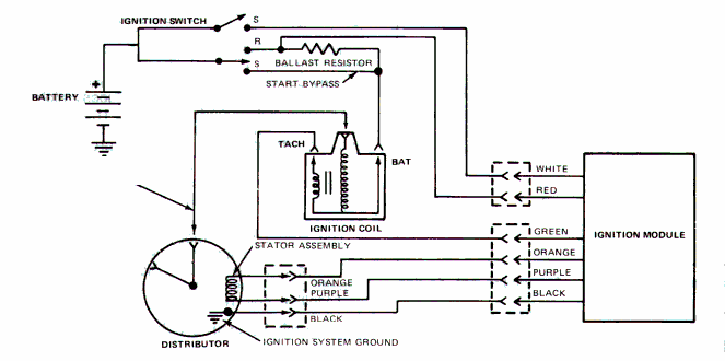
Ignition system wiring diagram showing battery, ignition switch, ballast resistor, coil, distributor stator and color-coded ignition module connections.
Part of 1980-1986 Ford Bronco Wiring Diagrams
This document is a schematic wiring diagram for a Ford Duraspark-style breakerless ignition system, showing the ignition module, distributor, ignition coil, ballast resistor, ignition switch, and battery. The ignition switch has S and R terminals; the R (run) circuit feeds through a ballast resistor to the ignition coil, while a start bypass circuit feeds the coil directly during cranking. The ignition coil is drawn with TACH and BAT terminals. The ignition module connects via two connectors: one with WHITE and RED wires going to the ignition switch/coil circuit, and one with GREEN, ORANGE, PURPLE, and BLACK wires. The ORANGE and PURPLE wires run to the stator assembly (magnetic pickup) inside the distributor, and the BLACK wire is the ignition system ground at the distributor. The GREEN wire connects to the coil's TACH (negative) side. A reader can learn the wire color functions at the ignition module connectors, how the ballast resistor and start bypass are arranged, and how the distributor stator assembly and system ground tie into the module. No year, model, engine, or part numbers are printed on the diagram itself; it was uploaded as applying to a 1982 Ford Bronco.
Is this accurate? Sign in to help verify it.
Frequently asked questions
- What wire colors connect the ignition module to the distributor?
- The module's connector has GREEN, ORANGE, PURPLE, and BLACK wires; the ORANGE and PURPLE wires go to the stator assembly in the distributor and the BLACK wire is the ignition system ground at the distributor.
- Which wires run between the ignition module and the ignition coil/switch circuit?
- A WHITE and a RED wire run from the ignition module toward the ignition switch and ballast resistor/coil circuit.
- How is the ballast resistor wired in this ignition system?
- The ballast resistor is fed from the ignition switch R terminal and supplies the ignition coil; a separate start bypass circuit from the switch's S terminal feeds the coil directly, bypassing the resistor.
- What terminals are shown on the ignition coil?
- The ignition coil is drawn with a TACH terminal and a BAT terminal.
- Where is the ignition system grounded in this diagram?
- The ignition system ground is shown at the distributor, via the BLACK wire from the module connector.






No comments yet.