Ford 5.0L/5.8L TFI Ignition System Wiring Diagram - EVTM Page 21-2 (Bronco)
Reference · 1987-1991 BroncoAll 175 wiring diagrams





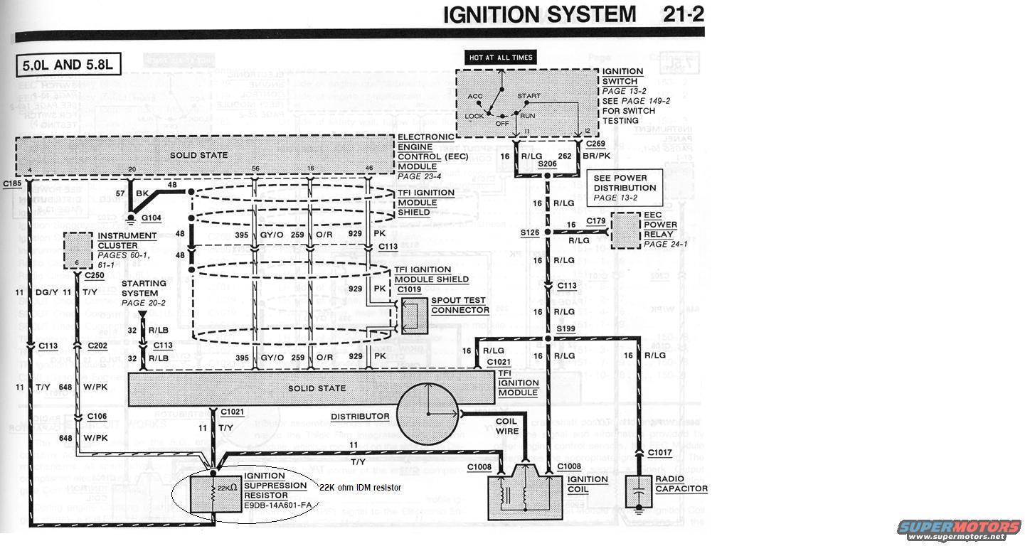
Wiring diagram of the 5.0L and 5.8L ignition system showing the EEC module, TFI module, distributor and coil with connector and wire codes.
Part of 1987-1991 Ford Bronco Wiring Diagrams
This is a scanned page (21-2, Ignition System) from a Ford Electrical & Vacuum Troubleshooting Manual (EVTM) showing the ignition system wiring diagram for 5.0L and 5.8L engines. The diagram traces power from the ignition switch (hot at all times, page 13-2) through circuit 16 R/LG and splices S206, S126, and S199 to the EEC Power Relay (page 24-1) and the TFI ignition module. It shows the Electronic Engine Control (EEC) module (page 23-4) connected via shielded TFI ignition module wiring using circuits 395 GY/O, 259 O/R, and 929 PK, plus a SPOUT test connector at C1019. Other circuits include 57 BK to ground G104, 32 R/LB to the starting system (page 20-2), 11 DG/Y and 11 T/Y to the instrument cluster (pages 60-1, 61-1), and 648 W/PK. Downstream components include the distributor, coil wire, ignition coil (C1008), radio capacitor (C1017), and a highlighted ignition suppression resistor, part number E9DB-14A601-FA, annotated as a "22K ohm IDM resistor" on the tach/IDM circuit 11 T/Y. Connectors identified include C185, C250, C113, C202, C106, C1021, C269, C179, and C1017. The page is useful for diagnosing TFI ignition, SPOUT, and IDM circuit problems.
Is this accurate? Sign in to help verify it.
Frequently asked questions
- What is the part number of the ignition suppression resistor in this diagram?
- E9DB-14A601-FA, shown as a 22KΩ resistor and annotated as a '22K ohm IDM resistor' on circuit 11 T/Y between the TFI ignition module and the instrument cluster.
- What wire colors run between the EEC module and the TFI ignition module?
- Shielded circuits 395 GY/O (gray/orange), 259 O/R (orange/red), and 929 PK (pink), plus circuit 16 R/LG for power and 11 T/Y for the IDM/tach signal.
- Which engines does this ignition diagram cover?
- The diagram is labeled for the 5.0L and 5.8L engines.
- Where is the SPOUT test connector in this circuit?
- The SPOUT test connector is on the 929 PK circuit, near connector C1019 at the TFI ignition module shield.
- How does the TFI ignition module get its power?
- Power comes from the ignition switch (hot at all times) on circuit 16 R/LG through splices S206, S126, and S199, which also feed the EEC Power Relay (see page 24-1 and Power Distribution page 13-2).






No comments yet.