1996 Ford Probe 2.5L PCM Connector C245 Pinout Diagram - Wire Colors & Functions

Reference · 1993-1997 ProbeAll 65 wiring diagrams
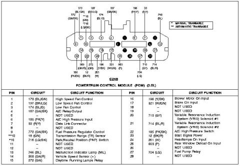
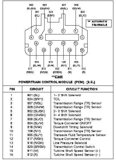
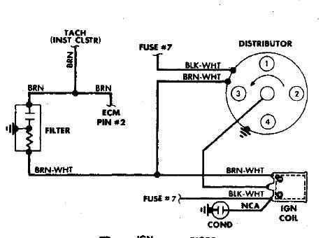
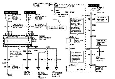
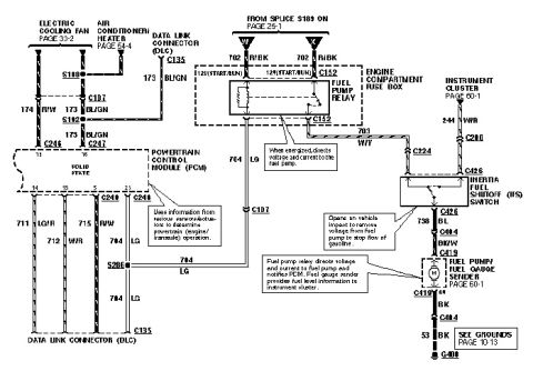









Powertrain control module connector C249 pinout with color-coded pins and circuit-function reference table.
Part of 1993-1997 Ford Probe Wiring Diagrams
This document is a connector pinout diagram and legend table for the Powertrain Control Module (PCM) connector labeled C245 on a Ford Probe with the 2.5L engine. The top portion shows a face view of the 28-position PCM connector with wire circuit numbers and wire color codes called out at each cavity (e.g., 173 BL/GN, 197 BR/LG, 746 BL). A legend distinguishes manual transaxle (*) from automatic transaxle (**) applications, which affects pin 10: circuit 18 (GN) Transmission Range (TR) Sensor for automatics versus circuit 716 (LG/BK) Park/Neutral Position (PNP) Switch for manuals. The table below lists all 28 pins with circuit number, wire color, and function, including High Speed Fan Control, Low Speed Fan Control, A/C Relay Output, A/C High Pressure Input, Data Link Connector, Fuel Pressure Regulator Control, Malfunction Indicator Lamp (MIL), Vehicle Speed Sensor (+), Daytime Running Lamps Relay, Blower Motor On Input, Brake On Input, VRIS Solenoids #1 and #2, A/C High Pressure Switch, Start Signal Power, Headlamps On Input, Rear Window Defrost On Input, and Fuel Pump Relay. Pins 5, 8, 11, 12, 18, 19, 26, and 28 are marked NOT USED. Useful for diagnosing cooling fans, VRIS, fuel pump relay, and A/C circuits at the PCM.
Is this accurate? Sign in to help verify it.
Frequently asked questions
- What is the PCM pin for the fuel pump relay on the 2.5L Probe?
- Pin 27, circuit 704 (LG - light green), is the Fuel Pump Relay control at connector C245.
- Which pins control the VRIS solenoids?
- Pin 20, circuit 718 (GY), controls Variable Resonance Induction System (VRIS) Solenoid #1, and pin 21, circuit 714 (BL/R), controls VRIS Solenoid #2.
- What are the cooling fan control pins on this PCM connector?
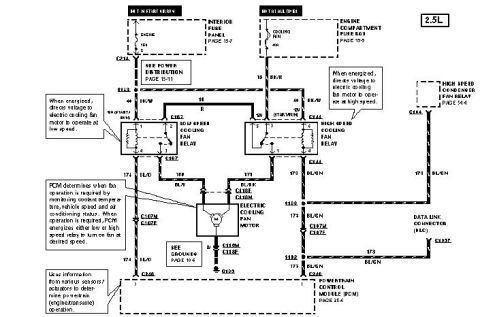
- Pin 1, circuit 173 (BL/GN) is High Speed Fan Control; pin 2, circuit 197 (BR/LG) is Low Speed Fan Control; and pin 3, circuit 174 (BL/LG) is Low Fan Control.
- Why does pin 10 show two different circuits?
- Pin 10 depends on the transaxle: automatic transaxle (**) uses circuit 18 (GN) for the Transmission Range (TR) Sensor, while manual transaxle (*) uses circuit 716 (LG/BK) for the Park/Neutral Position (PNP) Switch.
- Which pins on connector C245 are not used?
- Pins 5, 8, 11, 12, 18, 19, 26, and 28 are listed as NOT USED.






No comments yet.