SuperMotors SuperMotors SUPERMOTORS Search: try “orange Bronco on 35s”
Home/ Registry/ Ford/ Probe/ 1993-1997/ “parts”/ Photo supermotors.net/registry/media/844086

Pick-up coil resistance test and ignitor module test steps with…
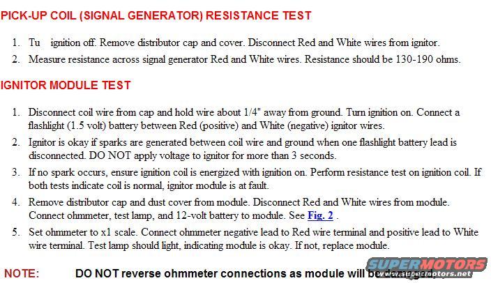
Pick-up coil resistance test and ignitor module test steps with wire colors and ohm specs
Pick-up coil resistance test and ignitor module test steps with wire colors and ohm specsOriginal file
Pick-up coil resistance test and ignitor module test steps with wire colors and ohm specs

Reference · 1993-1997 ProbeAll 12 service procedures
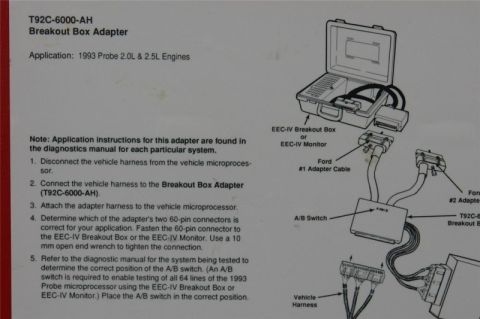
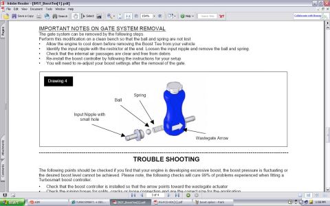
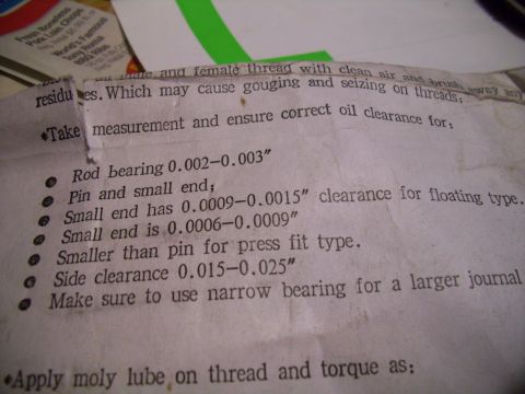
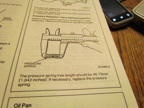
1993 Ford Probe Two Speed Cooling Fan Circuit Operation - 2.0L & 2.5L Pick-up coil resistance test and ignitor module test steps with wire colors and ohm specs Ford Probe Control Module Bench Test Diagram - Ohmmeter & Test Light Hookup 1995 Probe manual transaxle assembly procedure pages with shift lever and reverse lever steps Owner's manual page with HomeLink transceiver training steps 5 through 8 for a garage door opener Ford T92C-6000-AH Breakout Box Adapter Instructions - 1993 Probe 2.0L & 2.5L Turbosmart Boost Tee Instructions - Gate System Removal & Troubleshooting Connecting rod oil clearance instructions listing rod bearing, small end and side clearance figures Pressure regulator valve spring inspection with caliper measuring spring free length HomeLink Universal Transceiver owner's manual page with garage door opener training steps and illustration Handwritten-marked "Removal 101" checklist of fluid draining, radiator and wire harness removal steps ARP stud kit head installation procedure sheet with head stud and ARP moly assembly lubricant packet 12service procedures1993-1997 Ford Probe More reference 2000 Mazda 626 2.5L Engine Performance Wiring Diagram - PCM Pins & O2 SensorsWiring diagram 3-Position Rotary Selector Switch: Contact Positions #1 & #2 DiagramBrochure Tachometer Output from Coil Negative - 1N4004 Diode Rev Counter SchematicSchematic Ford 2012 MY vehicle emission control information label for a 5.0L gasoline engineSpec plate 1993 Ford Probe Compound Turbo & Intercooler Plumbing Routing DiagramVacuum routing 1993-94 Ford Probe Engine Bay Component Location Diagram - Relays, Fans, GroundsExploded parts Manual transaxle specifications screen with lubricant grade, 2.0L and 2.5L gear ratios and differential shim sManual page Hub Spacer Ring Blueprint - Ø77.75 OD x Ø72.00 ID x 6.35 Thick (Ford Probe)Blueprint Connecting Rod Bolt Torque Specs & Clearances - 8740 Cap Screw Instruction SheetTorque spec

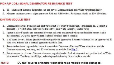
Test procedure for the pick-up coil (signal generator), 130-190 ohms across Red and White wires, and the ignitor module using a flashlight battery and ohmmeter.

Part of 1993-1997 Ford Probe Service Procedures

AI caption · Photo 56 of 676

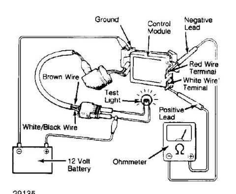
PICK-UP COIL (SIGNAL GENERATOR] RESISTANCE TEST 1 Tu lymmn oer Remme dlsmbutmr cap and (ma Dlsconnect Red and his wesom lgnltor 2 Measure reslstance across Slgnal generatm' Red and his wes Reslstance should be 130190 ohms IGNITUR MODULE TEST 1 Dtsconnect coll we som cap and hold we about 1 4 awzw Emu gound rum lgnmon on Connect a ashhght (1 5 u all) batterv between Red ([905th e) and his (negam e) lgnltor wes Ignltor ls okav lfspaeks are generated between coll we and yound when one ashhgut batterv lead ls dsconnected DO NOT applv oltage to 19mm for more than 3 seconds 3 Knospark occurs ensurelglmoncolllsenergzedwlthlylmnn on Pafm'm reslstance test on lgnmon col If both tests lnducate col ls normal lmtm' module ls at fault 4 Ranme dlsmbutnr cap and dust (ma 'om module Dlsconnect Red and his wesom module Connect ohmmeter test lamp and 124011 bane-(v to module See Fig. 2 5 Set ohmmeter to )1} scale Connect ohmmeter negame lead to Red we temnal and poslme lead to Mute we temnal Test lamp should 11le lndlcanng module ls mkav Knot replace module NOTE: DO NOT reverse ohmmeter connections as module will be damaged.

Is this accurate? Sign in to help verify it.
Comments

No comments yet.

More 1993-1997 Probes