Ford 3G Series Alternator Exploded Parts Diagram - Rebuild Component Guide

Reference · 1987-1991 BroncoAll 64 exploded parts diagrams
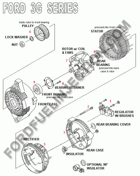










Exploded parts drawing of a Ford 3G series alternator showing pulley, rotor, stator, rectifier and case components.
Part of 1987-1991 Ford Bronco Exploded Parts Diagrams
This document is an exploded parts diagram of the Ford 3G series alternator, showing all major components in disassembled order along a central axis. Numbered callouts (1-9) identify the assembly sequence of parts: the regulator with brushes (1), a through-bolt (2), rear case (3), rear bearing (4), rectifier (5), pulley (6), rotor with coil and fans (7), bearing retainer (8), and front bearing (9). Additional labeled parts include the nut, lock washer, stator, front case, rear bearing cover, insulator, and an optional 90° insulator. The diagram includes helpful assembly notes: the pulley holds the rotor to the front bearing, the stator is pressed into the front case, the rear bearing is pressed into the back case and rotor, and the front bearing is pressed into the front case. The image is watermarked FORDFUELINJECTION.COM. A reader can learn the internal construction of the 3G alternator, the order of components for disassembly or rebuild, which parts are press-fit, and the names of each component, useful when rebuilding an alternator, replacing brushes/regulator, rectifier, or bearings, or performing a 3G alternator upgrade on a Ford vehicle.
Is this accurate? Sign in to help verify it.
Frequently asked questions
- What parts make up a Ford 3G series alternator?
- Per the diagram: nut, lock washer, pulley, front case, front bearing, bearing retainer, stator, rotor with coil and fans, rear bearing, rear bearing cover, regulator with brushes, rectifier, rear case, insulator, and an optional 90° insulator.
- Which parts of the 3G alternator are press-fit?
- The stator and front bearing are pressed into the front case, and the rear bearing is pressed into the back case and rotor.
- What holds the rotor to the front bearing on a 3G alternator?
- The pulley holds the rotor to the front bearing, secured by a lock washer and nut.
- Where are the brushes located in a Ford 3G alternator?
- The brushes are part of the regulator assembly, labeled 'REGULATOR W/ BRUSHES' (callout 1) mounted at the rear case.






No comments yet.