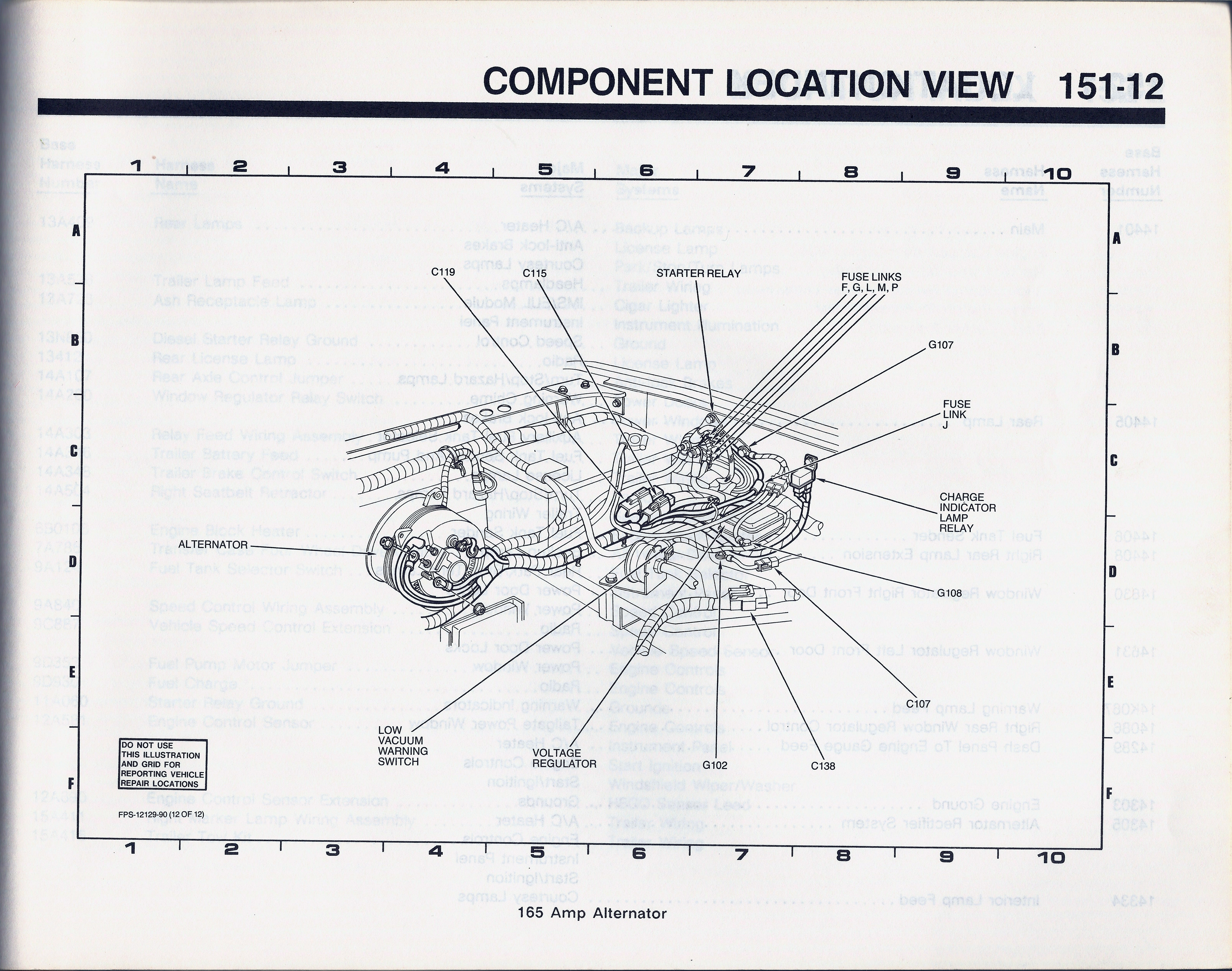
1990 Ford Bronco Component Location View 151-12-165 Amp Alternator Layout
Reference · 1987-1991 BroncoAll 111 schematics
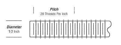
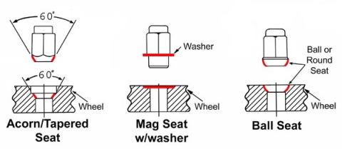
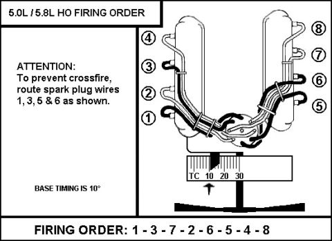














Ford EVTM component location view 151-12 for the 165-amp alternator charging system; maps alternator, voltage regulator, starter relay, charge indicator lamp relay, fuse links and connectors.
Part of 1987-1991 Ford Bronco Schematics
This document is page 151-12 of a Ford factory Component Location View series, captioned "165 Amp Alternator." It is a line-art illustration of the engine compartment charging-system area with a numbered/lettered locator grid (columns 1-10, rows A-F). Labeled callouts identify the physical locations of the alternator, voltage regulator, starter relay, charge indicator lamp relay, low vacuum warning switch, fuse links F, G, L, M and P, fuse link J, connectors C119, C115, C107 and C138, and ground points G102, G107 and G108. A boxed note warns not to use the illustration and grid for reporting vehicle repair locations. The footer code FPS-12129-90 (12 OF 12) indicates it is sheet 12 of a 12-sheet 1990 publication. A reader can use this page to find where the 165-amp alternator's related connectors, grounds, relays, and fusible links are physically located in the engine bay when tracing charging-system wiring on a 1990 Ford truck/Bronco. No fuse amperages, wire colors, or pin-outs are given; this page is strictly a component location reference intended to be used alongside the matching wiring schematics in the same manual set.
Is this accurate? Sign in to help verify it.
Frequently asked questions
- What does page 151-12 of the 1990 Ford component location views show?
- It shows the engine-compartment locations of the 165 Amp Alternator and related charging-system components, including the voltage regulator, starter relay, charge indicator lamp relay, and low vacuum warning switch.
- Which fuse links are identified on this diagram?
- Fuse links F, G, L, M, and P are shown together near the starter relay, and fuse link J is shown separately.
- Which connectors and grounds are labeled on the 165 amp alternator location view?
- Connectors C119, C115, C107, and C138, and ground points G102, G107, and G108.
- Can this grid be used to report vehicle repair locations?
- No. A boxed note states: 'DO NOT USE THIS ILLUSTRATION AND GRID FOR REPORTING VEHICLE REPAIR LOCATIONS.'
- Is this page part of a larger set?
- Yes, the footer code FPS-12129-90 (12 OF 12) indicates it is sheet 12 of 12 in the series.






No comments yet.