MegaSquirt MS I 2.2 Ignition Wiring Sketch - 1995 Ford Probe (Hand-Drawn)

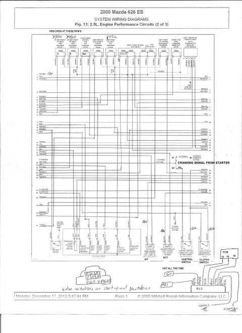
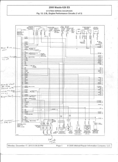
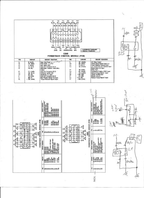
Reference · 1993-1997 ProbeAll 65 wiring diagrams
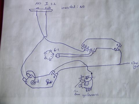

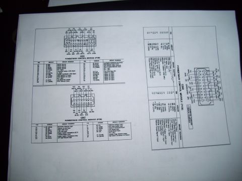
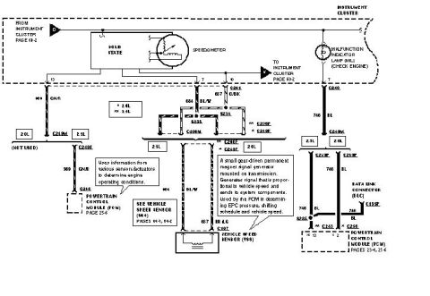
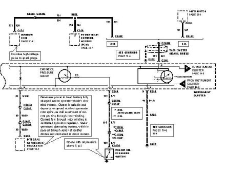
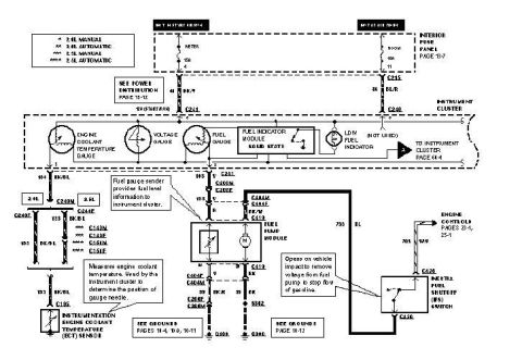




Hand-drawn wiring diagram of a MegaSquirt ECU connector layout showing grounds, ignition and 12V power.
Part of 1993-1997 Ford Probe Wiring Diagrams
This is a hand-drawn (pen on paper) wiring diagram documenting a MegaSquirt standalone engine management installation, labeled "MS I 2.2" (MegaSquirt I, version 2.2 board) with the annotation "inverted: NO." The sketch shows a top terminal strip with two labeled connections (pin 24 and "fidle", likely fast idle), a round distributor-style component labeled "6-1", and several connectors with pin labels including B, R, E, N, and an unknown pin marked "?", plus pins labeled "c" and "x" on a right-hand connector. Two components at the lower left show pins labeled "w", "g", "c", "B" and grounds marked "(+) grd". A coil is sketched at lower right with (+) and (-) terminals, fed by "12v. from ign harness," and a separate wire labeled "12v. ign" runs off the right edge of the page. A reader can learn the rough routing of MegaSquirt ignition-input wiring between the distributor, igniter/connectors, coil, and 12V ignition power sources as installed on the uploader's vehicle, though no wire colors, part numbers, or formal pinout tables are provided.
Is this accurate? Sign in to help verify it.
Frequently asked questions
- What MegaSquirt version does this diagram cover?
- The diagram is labeled "MS I 2.2", indicating a MegaSquirt I with a version 2.2 board.
- Is the ignition input inverted in this setup?
- No: the diagram explicitly notes "inverted: NO".
- Where does the coil get its power in this diagram?
- The coil is shown receiving "12v. from ign harness," and a separate wire labeled "12v. ign" runs to a connector on the right side of the diagram.
- What pin labels are shown on the connectors?
- One multi-pin connector shows pins B, R, E, N and one unknown pin marked "?"; another connector shows pins c and x; lower components show pins w, g, c, B, and two grounds marked "(+) grd". The top terminal strip shows pin 24 and "fidle".






No comments yet.