Home/
Registry/
Ford/
Bronco/
1992-1996/
“pukin' dogII”/
Photo
supermotors.net/registry/media/877808
1996 Ford Bronco Hood Latch & Release Cable Routing Diagram (N9805-D)

Reference · 1992-1996 BroncoAll 169 exploded parts diagrams
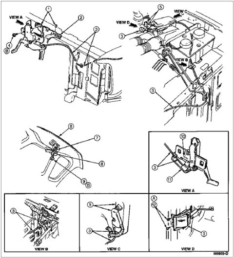




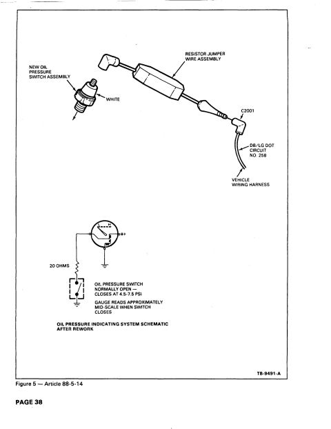
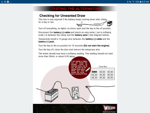
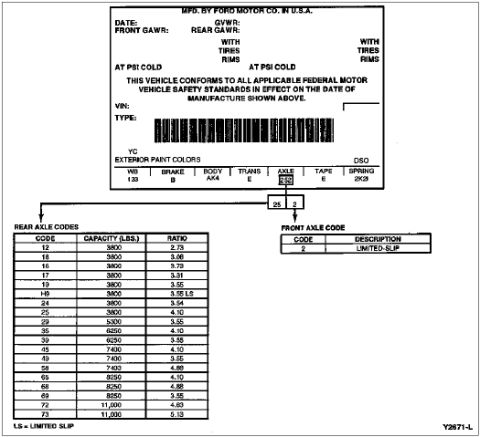
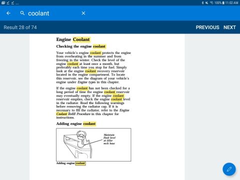

Component install drawing of the hood latch and release linkage with numbered callouts and detail views A through D.
Part of 1992-1996 Ford Bronco Exploded Parts Diagrams
This document is a single-page exploded/component-location illustration showing the hood latch and hood latch release cable installation, apparently for a Ford truck (uploaded as applying to a 1996 Ford Bronco). The main drawing at top depicts the cable routing along the inner fender/firewall area from the hood latch assembly at the front of the vehicle (View A, left) toward the passenger compartment, with a second perspective at top right showing the engine compartment near the coolant reservoir and battery area (Views B, C, D indicated by arrows). A middle-left inset shows the interior release handle mounted under the instrument panel at the kick panel/steering column area (callouts 6, 7, 8, 9). Four detail insets along the bottom and right, View B, View C, View A, and View D, show close-ups of cable clips/retainers (callout 3 appears repeatedly), the latch mechanism (callouts 10, 11), and a bracket-mounted component (callout 12). Numbered callouts 1-12 identify individual parts, but no legend or parts list is printed on this page, so component names and part numbers must come from an accompanying page. The only identifying text is the Ford illustration code N9805-D.
Is this accurate? Sign in to help verify it.
Frequently asked questions
- What does this diagram show for the 1996 Ford Bronco?
- It shows the hood latch assembly and hood release cable routing, including cable clips along the fender/firewall (callout 3), the latch mechanism (callouts 10 and 11 in View A), and the interior release handle under the dash (callouts 6-9).
- Does this diagram include a parts list or part numbers?
- No. It only contains numbered callouts 1-12, view labels (View A through View D), and the illustration reference code N9805-D. No legend or part numbers are printed on this page.
- Where is the interior hood release handle located according to the diagram?
- The middle-left inset shows the release handle mounted inside the cab under the instrument panel near the kick panel/steering column area, identified by callouts 6, 7, 8, and 9.
- What is the illustration reference number on this diagram?
- N9805-D, printed in the bottom right corner.






No comments yet.