Home/
Registry/
Ford/
Bronco/
1992-1996/
“pukin' dogII”/
Photo
supermotors.net/registry/media/877799
1996 Ford Bronco DRL Control Module Location Diagram (Ford K17369-D)

Reference · 1992-1996 BroncoAll 169 exploded parts diagrams
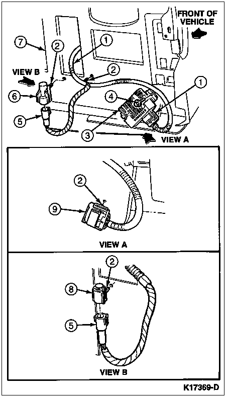



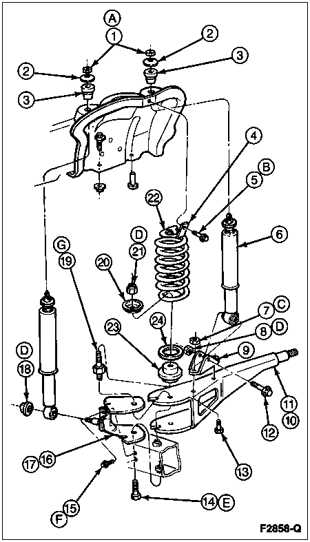
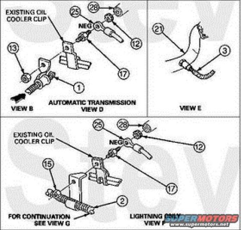

Component-location install drawing showing a harness/sensor connector with numbered callouts and detail views A and B.
Part of 1992-1996 Ford Bronco Exploded Parts Diagrams
This document is an illustration (Ford service-manual style, figure number K17369-D) showing the mounting location of a module and its wiring harness connectors on a vehicle, uploaded as the Daytime Running Lamp (DRL) control module location for a 1996 Ford Bronco. The main view shows the module (callout 4) mounted on a bracket/panel area with directional arrow indicating 'FRONT OF VEHICLE,' along with a wiring harness (callout 1), fasteners/screws (callout 2), and numbered components 3, 5, 6, and 7. Two enlarged insets are provided: VIEW A shows a connector (callout 9) with a fastener (callout 2) and harness routing; VIEW B shows two mating connectors (callouts 8 and 5) with a fastener (callout 2) and the harness. The illustration contains no legend text identifying the numbered parts, no part numbers other than the figure number, and no torque values or wire colors. It is useful for locating the module and its electrical connectors relative to the front of the vehicle and understanding how the harness is routed and secured.
Is this accurate? Sign in to help verify it.
Frequently asked questions
- Where is the DRL control module located on a 1996 Ford Bronco?
- Per this diagram, the module (callout 4) mounts to a bracket/panel with its harness routed nearby; the arrow labeled 'FRONT OF VEHICLE' orients the view toward the front, indicating a forward under-hood/inner panel location.
- What do VIEW A and VIEW B show in this diagram?
- VIEW A is an enlarged view of a connector (callout 9) secured by a fastener (callout 2); VIEW B is an enlarged view of two mating connectors (callouts 8 and 5) with a fastener (callout 2) and harness routing.
- Does the diagram identify the numbered parts by name?
- No. The illustration uses numbered callouts (1 through 9) but no legend or parts list text is included in this scan.
- What is the Ford figure number for this illustration?
- The figure is identified as K17369-D in the lower right corner.






No comments yet.