Home/
Registry/
Ford/
Bronco/
1987-1991/
1989 Ford Bronco/
Photo
supermotors.net/registry/media/881385
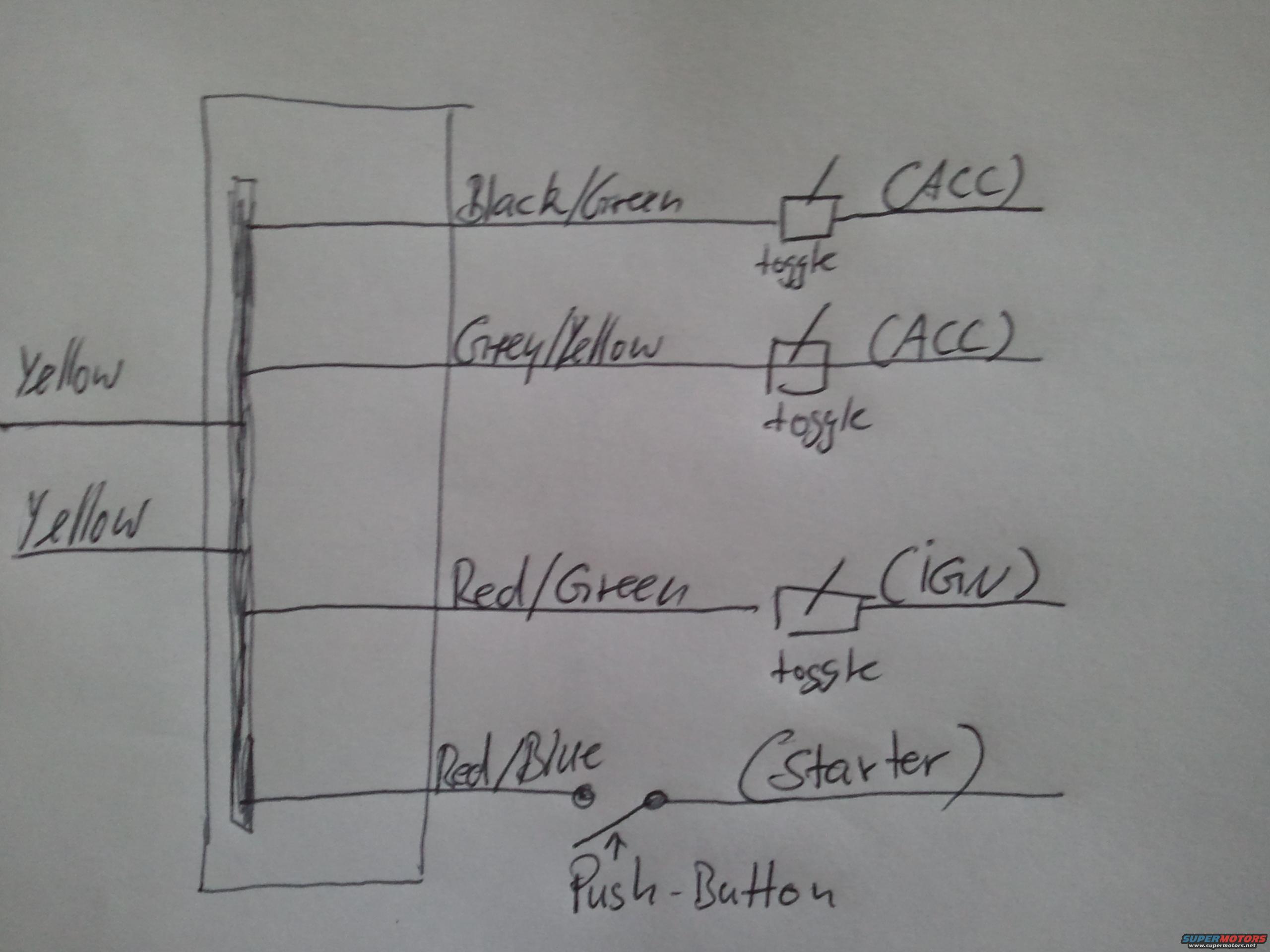
1989 Ford Bronco Ignition Switch Bypass Wiring Diagram - Toggle & Push-Button
Reference · 1987-1991 BroncoAll 175 wiring diagrams






Hand-drawn wiring diagram showing color-coded ignition wires to toggle switches for ACC, IGN and a push-button starter.
Part of 1987-1991 Ford Bronco Wiring Diagrams
This is a hand-drawn wiring diagram, uploaded to the gallery of a 1989 Ford Bronco, showing a simple ignition-switch bypass or replacement scheme using toggle switches and a push-button. On the left, two wires labeled 'Yellow' feed into a drawn connector/switch block (apparently the power feeds). From the block, four output circuits are drawn: a Black/Green wire routed through a toggle switch to an (ACC) accessory circuit; a Grey/Yellow wire routed through a second toggle switch to another (ACC) accessory circuit; a Red/Green wire routed through a third toggle switch to the (IGN) ignition circuit; and a Red/Blue wire routed through a momentary push-button to the (Starter) circuit. A reader can learn which ignition-harness wire colors correspond to accessory, ignition, and starter functions in this setup, and how to wire toggle switches for ACC/IGN and a push-button for the starter to start the vehicle without the original key switch. The sketch contains no part numbers, fuse ratings, dates, or explicit vehicle-model identification.
Is this accurate? Sign in to help verify it.
Frequently asked questions
- Which wire color goes to the starter in this diagram?
- The Red/Blue wire connects through a push-button to the (Starter) circuit.
- What wire controls the ignition (IGN) circuit?
- The Red/Green wire, routed through a toggle switch, feeds the (IGN) circuit.
- Which wires are used for the accessory (ACC) circuits?
- Two wires: Black/Green and Grey/Yellow, each through its own toggle switch, feed (ACC) circuits.
- What type of switch is used for the starter versus the other circuits?
- The starter uses a momentary push-button, while the ACC and IGN circuits each use toggle switches.
- What are the input feed wires shown on the left side?
- Two wires labeled 'Yellow' feed into the connector/switch block on the left of the diagram.






No comments yet.