1996 Ford Probe Oxygen Sensor, CKP & Knock Sensor Wiring Diagram (PCM)
Reference · 1993-1997 ProbeAll 65 wiring diagrams
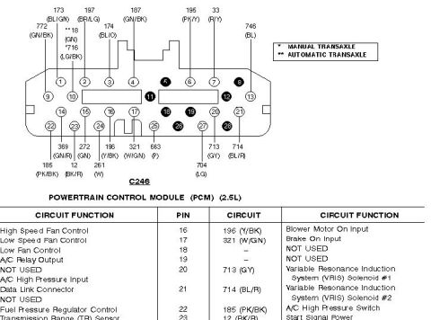
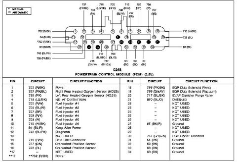
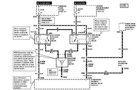
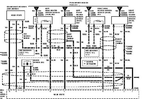
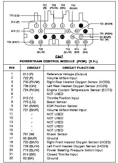
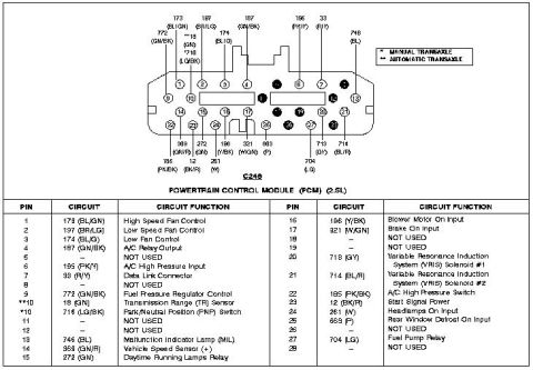
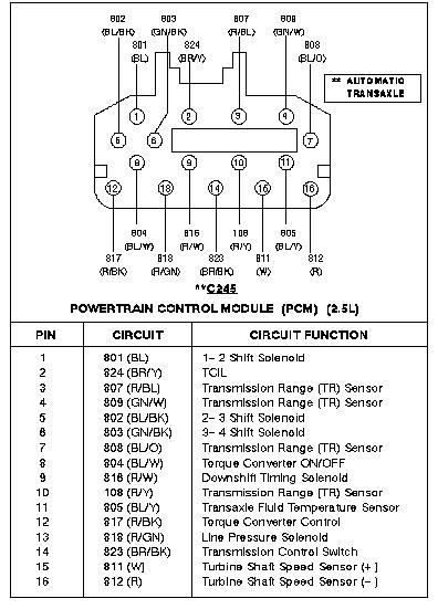









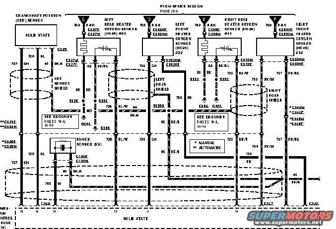
Wiring diagram showing crankshaft position sensor, heated oxygen sensors and knock sensor circuits with color codes.
Part of 1993-1997 Ford Probe Wiring Diagrams
This is a scanned engine-control wiring diagram page showing the crankshaft position (CKP) sensor, four heated oxygen sensors (HO2S), and the knock sensor (KS) circuits connecting to the powertrain control module (PCM, shown as a solid-state module at the bottom). It was uploaded to a Ford Probe gallery with the filename '1996 probe.JPG'. The diagram identifies four oxygen sensors: Left Rear HO2S #21 (connector C127F/C127M), Left Front HO2S #22 (C1024F/C1024M), Right Rear HO2S #11 (C104F/C104M), and Right Front HO2S #12 (C1030F/C1030M), each fed by circuit 702 R/BK from splice S122 (referenced on page 25-9). Wire circuit numbers and colors are shown, including 726 GN, 727 GN, 65 BL, 62/63 BK/BL, 60/80 BK, 734 GN, 736 BL/W, 738 PK, 735 PK/W, 737 PK/BL, 64 BK/R, and 761 W. Shielded wiring is indicated for the CKP sensor and both HO2S banks. Ground references point to pages 14-9, 10-10 and 10-1, 10-14, with grounds G104 and G108 and splices S110/S101/S1010 shown. Manual vs. automatic transmission connector variants (C120/C121, C142/C144) are keyed with asterisks. PCM connectors C244, C247, and C248 with pin numbers appear along the bottom.
Is this accurate? Sign in to help verify it.
Frequently asked questions
- What connectors are used for the four heated oxygen sensors in this diagram?
- Left Rear HO2S #21 uses C127F/C127M, Left Front HO2S #22 uses C1024F/C1024M, Right Rear HO2S #11 uses C104F/C104M, and Right Front HO2S #12 uses C1030F/C1030M.
- What wire circuit powers the heated oxygen sensors?
- Circuit 702 R/BK (red/black) feeds all four heated oxygen sensors, coming from splice S122 referenced on page 25-9.
- What connector does the knock sensor use and what are its wire colors?
- The knock sensor (KS) connects through C138F/C138M with wires 65 BK/R and 761 W.
- Are there differences between manual and automatic transmission wiring in this diagram?
- Yes. A legend marks * for MANUAL and ** for AUTOMATIC; automatic-specific connectors include C121E/C121M, C120E/C120M, C142M/C142F, and C144M/C144F.
- Which PCM connectors are shown at the bottom of the diagram?
- The bottom of the diagram shows connectors C244, C247, and C248 entering the solid-state powertrain control module, with pin numbers such as 15, 14, 16, 13, 10, 18, 8, and 2.






No comments yet.