Ford DuraSpark II Ignition Wiring Diagram - Module, Coil & Resistor Schematic
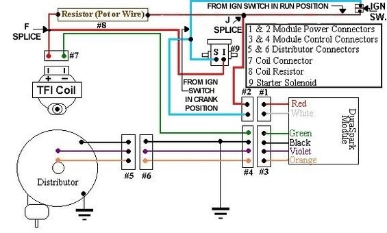
Wiring diagram showing TFI coil and Duraspark module circuits with color-coded wires and numbered connector pins.
This document is a hand-drawn color wiring schematic for a Ford DuraSpark II ignition system. It shows how the DuraSpark module connects to the distributor, TFI coil, ballast resistor, ignition switch, and starter solenoid. A numbered legend identifies nine callouts: connectors 1 & 2 are the module power connectors, 3 & 4 the module control connectors, 5 & 6 the distributor connectors, 7 the coil connector, 8 the coil resistor (labeled 'Resistor (Pot or Wire)'), and 9 the starter solenoid (with S and I terminals). Two ignition-switch feeds are shown: one from the ignition switch in the RUN position (through the resistor via the F splice and J splice) and one from the ignition switch in the CRANK position (from the solenoid I terminal, bypassing the resistor). Module wire colors are identified as Red, White, Green, Black, Violet, and Orange. The distributor connects to the module through connectors #5 and #6, and grounds are shown for the distributor and module circuits. A reader can learn the complete wiring path, connector functions, and wire color coding needed to install or troubleshoot a DuraSpark II ignition conversion.
Is this accurate? Sign in to help verify it.
Frequently asked questions
- What do the numbered connectors in the DuraSpark II schematic represent?
- Per the legend: 1 & 2 are module power connectors, 3 & 4 are module control connectors, 5 & 6 are distributor connectors, 7 is the coil connector, 8 is the coil resistor, and 9 is the starter solenoid.
- What wire colors go to the DuraSpark module?
- The diagram labels Red, White, Green, Black, Violet, and Orange wires at the module connectors.
- How is the coil resistor wired in this system?
- The resistor (pot or wire), callout #8, is fed from the ignition switch in the RUN position and connects through the F splice to the coil connector (#7) at the TFI coil.
- How does the coil get full voltage during cranking?
- A wire from the ignition switch in the CRANK position feeds through the starter solenoid's I terminal (#9), bypassing the resistor to supply the coil while cranking.
- Where does the distributor connect to the module?
- The distributor wires pass through connectors #5 and #6 to the module control connectors #4 and #3 on the DuraSpark module.
Comments
More from this build














No comments yet.