SuperMotors SuperMotors SUPERMOTORS Search: try “orange Bronco on 35s”
Home/ Registry/ Ford/ Bronco/ 1987-1991/ “Eddie Bauer”/ Photo supermotors.net/registry/media/871477

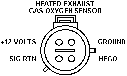
Ford HEGO Heated Oxygen Sensor Connector Pinout Diagram - 1990 Bronco EFI

Heated exhaust gas oxygen sensor connector pinout showing +12 volts, ground, signal return, and HEGO terminals
Heated exhaust gas oxygen sensor connector pinout showing +12 volts, ground, signal return, and HEGO terminalsOriginal file
Heated exhaust gas oxygen sensor connector pinout showing +12 volts, ground, signal return, and HEGO terminals

Reference · 1987-1991 BroncoAll 175 wiring diagrams

1990 Ford Bronco Anti-Lock Brakes (RABS) Wiring Diagram - EVTM Page 42-2 1989-95 Ford MAF Sensor Connector Pinout Diagram - Wire Colors & Pins A-D Ford TFI Module Connector Pinout - 4.9L 5.0L 5.8L Wire Colors & Circuits Ford HEGO Heated Oxygen Sensor Connector Pinout Diagram - 1990 Bronco EFI 1995 Ford Bronco TFI Ignition Control Module Connector C1021 Pinout Diagram 1995 Ford Bronco C103 In-Line Connector Pinout - EVTM Page 150-2 1995 Ford Bronco TR Sensor (MLPS) Testing - E4OD/4R70W Pinout & Ohm Values 1995 Ford Bronco E4OD Transmission Wiring Diagram - Solenoids, PCM Pins (30-2) Ford 3G Alternator Wiring Diagram - Mega Fuse, Charge Lamp & Wire Colors KC Driving Lights & LED Light Bar Relay Wiring Diagram - Ford Bronco Aux Lights 175wiring diagrams1987-1991 Ford Bronco More reference Ford Thermactor Air Bypass Valve Cutaway Diagram - Port IdentificationSchematic Ford Canister Purge Regulator Valve (CANP 9C915) Test Procedure - Figure 11Service procedure Ford 5.8L important engine information decal with 10° BTDC timing check and ASF-32C plugSpec plate Ford 5.0L V8 PCV Valve & Hose Routing Diagram - 9A474, 6B890, 6A664Exploded parts Ford 5.0L/5.8L Air Throttle Body Assembly Diagram - Canister Purge Ports & TPSManual page 1990 Bronco Major Standard Equipment sheet with interior features and functional specs by trimBrochure Borgeson Steering Intermediate Shaft Measurement Diagram - U-Joint Length B & CBlueprint Ford Thermactor Combination Valve Diagram - Air Bypass/Control Ports LabeledVacuum routing 1990 Ford Bronco Fuse Panel Diagram: Fuse Positions, Amps & Circuits (11-2)Fuse chart Ford V8 Intake Manifold Bolt Tightening Sequence Diagram - Stud LocationsTorque spec

HEGO sensor connector pinout diagram labeling the +12 volts, ground, signal return, and HEGO signal terminals.

Part of 1987-1991 Ford Bronco Wiring Diagrams

AI caption · Photo 713 of 1787

This document is a simple connector pinout diagram for a Heated Exhaust Gas Oxygen (HEGO) sensor, uploaded as reference material for a 1990 Ford Bronco. The illustration shows a face view of the round 4-pin HEGO sensor connector with each terminal labeled by function. The top-left pin is labeled +12 VOLTS (power for the sensor heater), the top-right pin is GROUND, the bottom-left pin is SIG RTN (signal return), and the bottom-right pin is HEGO (the oxygen sensor signal output). No wire colors, part numbers, torque values, or vehicle applicability information is printed on the diagram itself. A reader can use this diagram to identify which terminal in the harness or sensor connector corresponds to heater power, heater/sensor ground, signal return, and the HEGO signal, useful when testing the sensor with a multimeter, diagnosing oxygen sensor circuit codes, or repairing/repinning the connector. It is part of a larger album of Ford EEC-IV EFI reference diagrams (MAF, ECT, EEC-IV connector, speed density schematics) filed with the owner's 1990 Ford Bronco documentation.

Is this accurate? Sign in to help verify it.

Frequently asked questions

What are the four pins on the HEGO (heated oxygen sensor) connector?
The diagram labels the four pins as +12 VOLTS, GROUND, SIG RTN (signal return), and HEGO (sensor signal).
Which pin carries the oxygen sensor signal?
The pin labeled HEGO, shown at the lower right of the connector face view, is the sensor signal output.
Where is the +12 volt heater power pin on the HEGO connector?
The +12 VOLTS pin is shown at the upper left of the connector in the face view, opposite the GROUND pin on the upper right.
Does the diagram show wire colors for the HEGO connector?
No, the diagram only labels pin functions (+12 VOLTS, GROUND, SIG RTN, HEGO); no wire colors are shown.


Comments

No comments yet.

More 1987-1991 Broncos